background image

Introduction

ATCA-7368 Installation and Use (6806800M12C

)

26

Figure 1-1

Declaration of Conformity 

Содержание ATCA-7368

Страница 1: ...Embedded Computing for Business Critical ContinuityTM ATCA 7368 Installation and Use P N 6806800M12C February 2014 ...

Страница 2: ...his document and to make changes from time to time in the content hereof without obligation of Emerson to notify any person of such revision or changes Electronic versions of this material may be read online downloaded for personal use or referenced in another document as a URL to a Emerson website The text itself may not be published commercially in print or electronic form edited translated or o...

Страница 3: ...quirements 34 2 3 1 Environmental Requirements 35 2 3 2 Power Requirements 36 2 4 Blade layout 38 2 5 Installing the Blade Accessories 39 2 5 1 DIMM Memory Modules 39 2 5 2 PMEM and SATA Module 41 2 5 3 USB 2 0 Flash Module 43 2 6 Installing and Removing the Blade 44 2 6 1 Installing the Blade 45 2 6 2 Removing the Blade 48 3 Controls Indicators and Connectors 51 3 1 Overview 51 3 2 Faceplate 51 3...

Страница 4: ...evice 64 4 4 3 By Boot Selection Menu 65 4 4 4 Network boot 65 4 5 Redirection of I O 66 4 5 1 Redirection of the I O to COM ports Console Redirection 66 4 6 LED behavior during POST 67 4 7 LED Usage 67 4 8 RTM SAS Controller 67 4 9 Board Information Display 68 4 10 USB Ports 68 4 11 Supported Operating Systems 68 4 12 Persistent Memory Module 69 4 13 Upgrading the BIOS 69 4 14 BIOS Error Messages...

Страница 5: ...Single Width Mid size AMC 87 6 Serial Over LAN 89 6 1 Overview 89 6 2 Installing the ipmitool 89 6 3 Configuring SOL Parameters 90 6 3 1 Using Standard IPMI Commands 90 6 3 2 Using ipmitool 91 6 4 Establishing a SOL Session 93 7 Supported IPMI Commands 95 7 1 Overview 95 7 2 Standard IPMI Commands 95 7 2 1 Global IPMI Commands 95 7 2 2 System Interface Commands 96 7 2 3 Watchdog Commands 96 7 2 4 ...

Страница 6: ...mand 125 7 5 5 Set Debug Level Command 126 7 5 6 Get Hardware Address Command 127 7 5 7 Set Hardware Address Command 127 7 5 8 Get Handle Switch Command 128 7 5 9 Set Handle Switch Command 129 7 5 10 Get Payload Communication Time Out Command 129 7 5 11 Set Payload Communication Time Out Command 130 7 5 12 Enable Payload Control Command 131 7 5 13 Disable Payload Control Command 131 7 5 14 Reset I...

Страница 7: ... 141 8 5 Sensor Data Records 142 9 Sensor Data Records 199 9 1 Overview 199 9 2 Sensor Data Records 199 A Replacing the Battery 207 A 1 Replacing the Battery 207 B Related Documentation 211 B 1 Emerson Network Power Embedded Computing Documents 211 B 2 Related Specifications 212 Safety Notes 213 Sicherheitshinweise 217 ...

Страница 8: ...ATCA 7368 Installation and Use 6806800M12C Contents 8 Contents Contents ...

Страница 9: ... 4 5 SEC Status Codes 70 Table 4 6 PEI Status Codes 71 Table 4 7 DXE Status Codes 74 Table 5 1 Ethernet Controller Types 83 Table 6 1 SOL Parameters 90 Table 7 1 Supported Global IPMI Commands 95 Table 7 2 Supported System Interface Commands 96 Table 7 3 Supported Watchdog Commands 97 Table 7 4 Supported SEL Device Commands 97 Table 7 5 Supported FRU Inventory Commands 98 Table 7 6 Supported Senso...

Страница 10: ...ble 7 33 Set Serial Interface Properties Command Description 124 Table 7 34 Get Debug Level Command Description 125 Table 7 35 Set Debug Level Command Description 126 Table 7 36 Get Hardware Address Command Description 127 Table 7 37 Set Hardware Address Command Description 127 Table 7 38 Get Handle Switch Command Description 128 Table 7 39 Set Handle Switch Command Description 129 Table 7 40 Get ...

Страница 11: ...mps 151 Table 8 11 Holdup Cap Volts 153 Table 8 12 Input Power 154 Table 8 13 PWR Status 155 Table 8 14 Inlet Temp 156 Table 8 15 Outlet Temp 159 Table 8 16 IPMC Temp 162 Table 8 17 CPU Temp 163 Table 8 18 DDR 1 Temp 166 Table 8 19 DDR 2 Temp 167 Table 8 20 DDR 3 Temp 168 Table 8 21 DDR 4 Temp 170 Table 8 22 DDR 5 Temp 171 Table 8 23 DDR 6 Temp 172 Table 8 24 12 0V 174 Table 8 25 3 3V 175 Table 8 ...

Страница 12: ...ror 191 Table 8 39 Boot Inited 192 Table 8 40 POST Code 193 Table 8 41 IPMC Status 194 Table 8 42 Power Good 195 Table 8 43 Boot Bank 196 Table 8 44 Reset Source 197 Table 8 45 CPU Status 198 Table 9 1 Sensor Data Records 199 Table B 1 Emerson Network Power Embedded Computing Publications 211 Table B 2 Related Specifications 212 ...

Страница 13: ...1 Faceplate 51 Figure 3 2 Faceplate LEDs 52 Figure 3 3 USB2 0 Flash Disk module connector pinout 56 Figure 4 1 Main Menu 63 Figure 5 1 Block Diagram 77 Figure 5 2 Nehalem Westmere Processor block diagram 78 Figure 5 3 ICH10R Diagram 81 Figure 5 4 SFMEM 7221 Module dimensions bottom view 82 Figure 5 5 Overall SMBus Connections 86 Figure 6 1 SOL Overview 89 Figure 7 1 System Boot Options Parameter 1...

Страница 14: ...ATCA 7368 Installation and Use 6806800M12C 14 List of Figures ...

Страница 15: ...tors on page 51 describes external interfaces of the blade This includes connectors and LEDs BIOS on page 59 describes the features and setup of BIOS FunctionalDescriptiononpage77describesthefunctionalblocksofthebladeindetail This includes a block diagram description of the main components used and so on Serial Over LAN on page 89 provides information on how to establish a serial over LAN session ...

Страница 16: ...Blade Services BGA Ball Grid Array BIOS Basic Input Output System BOM Bill of Material CFM Cubic Feet per Minute CG Carrier grade CK409B Clock generator standard for Intel chipset platforms CPLD Complex Programmable Logic Device CPM Critical Parameter Management CPU Central Processing Unit DDR Dual Data Rate type of SDRAM DDR3 Double Data Rate 3 synchronous dynamic random access memory SDRAM is th...

Страница 17: ...t GPIO General Purpose Input Output I2C Inter Integrated Circuit Bus 2 wire serial bus and protocol I O Input Output IA 32 32 bit Intel processor architecture ICH I O Control Hub also called South Bridge ICT In circuit Test IMC Integrated Memory Controller IPMB Intelligent Platform Management Bus IPMB L The IPMB connecting the carrier IPMC to the AMC module Intel QuickPath Interconnect Intel QPI A...

Страница 18: ... ps Megabits per second MB ps Megabytes per second MCH Memory Controller Hub also called North Bridge MHz Megahertz MMC Module Management Controller Module This term is used to refer to the Module card in this document MP Management Power MTBF Mean Time Between Failures MTTR Mean Time To Repair N A Not Applicable NEBS Network Equipment Building System NMI Non maskable Interrupt NT Non transparent ...

Страница 19: ...unication interface SATA Serial AT Attachment high speed serial interface standard for storage devices SDR Sensor Data Record SDRAM Synchronous Dynamic Random Access Memory SELV Safety Extra Low Voltage SerDes Serializer Deserializer SIMD Single Instruction Multiple Data SMBus System Management Bus SMI System Management Interrupt SODIMM Small Outline Dual in line Memory Module SPD Serial Presence ...

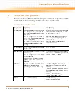
Страница 20: ...or hexadecimal numbers digits are 0 through F for example used for addresses and offsets 0b0000 Same for binary numbers digits are 0 and 1 bold Used to emphasize a word Screen Usedforon screenoutputandcoderelatedelements or commands in body text Courier Bold Used to characterize user input and to separate it from system output Reference Used for references and for table and figure descriptions Fil...

Страница 21: ...sed in registers Logical OR Indicates a hazardous situation which if not avoided could result in death or serious injury Indicates a hazardous situation which if not avoided may result in minor or moderate injury Indicates a property damage message No danger encountered Pay attention to important information Notation Description ...

Страница 22: ...6800M12B January 2012 Final version Added Declaration of Conformity on page 26 Updated Chapter 1 Mechanical Data on page 27 Updated Chapter 2 Environmental and Power Requirements on page 34 Table Power Requirements on page 37 and Figure Blade Layout on page 38 Updated Chapter 4 Overview on page 59 Updated Table Ethernet Controller Types on page 83 Table Power Configuration on page 141 Table 48V A ...

Страница 23: ...provides system management capabilities and is hot swap compatible based on the ATCA specification The following lists the main features of ATCA 7368 Form factor Single slot ATCA 280mm x 322mm Processor Intel Westmere EP Six Core processor Intel Xeon 5600 series Drop in compatible with Intel Nehalem EP processor Intel Xeon 5500 Series North Bridge Xeon 5520 Tylersburg IOH36 D Provides two QPI inte...

Страница 24: ...and 4 MB Recovery Boot Flash SPI Onboard storage support optional SATA Cube SSD 16 32 64 128 GB capacity USB flash EUSB SDD 1 2 or 4 GB capacity Onboard IPMC IPMI management controller implements IPMI version 1 5 Onboard Glue Logic FPGA for IPMC extension and onboard Control register 1 2 Standard Compliances The product is designed to meet the following standards Table 1 1 Standard Compliances Sta...

Страница 25: ...2 EMC requirements on system level Attention ATCA boards require CISPR 22 Class B on conducted emissions EMC immunity requirements industrial EMC for telecom equipment EN 55024 EN 61000 6 2 EN 300386 FCC Part 15 Class A ANSI IPC A 610 Rev B Class 2 Manufacturing requirements ANSI IPC R 700B ANSI J 001 003 ISO 8601 Y2K compliance NEBS Standard GR 63 CORE NEBS level three Project is designed to supp...

Страница 26: ...Introduction ATCA 7368 Installation and Use 6806800M12C 26 Figure 1 1 Declaration of Conformity ...

Страница 27: ...bouttheblade smechanicaldata suchasdimensionsand weight Table 1 2 Mechanical Data Feature Value Dimensions width x height x depth Single slot ATCA 280mm x 322mm PCBA size 280mm x 322 25mm Assembly size 351mm x 312mm x 30mm 8U form factor Weight of blade with AMC 3053 5g Weight of blade without AMC and HDD 2862 3g ...

Страница 28: ...Introduction ATCA 7368 Installation and Use 6806800M12C 28 1 4 Mechanical Layout The following graphics illustrate the mechanical layout of the blade Figure 1 2 Mechanical Layout with AMC ...

Страница 29: ...Introduction ATCA 7368 Installation and Use 6806800M12C 29 Figure 1 3 Mechanical Layout without AMC and HDD ...

Страница 30: ...Introduction ATCA 7368 Installation and Use 6806800M12C 30 Figure 1 4 Mechanical Layout without AMC with HDD ...

Страница 31: ...nal onboard hdd no AMC site no Flash ROHS 6 6 ATCA 7368 0GB CE Commercial ATCA blade Intel Xeon E5645 6 CORE 2 4 GHZ 0GB 10G support AMC site no Flash ROHS 6 6 ATCA 7368 0GB LS CE Commercial ATCA blade Intel Xeon E5645 6 CORE 2 4 GHZ 0GB 10G support optional onboard HDD NO amc site no Flash ROHS 6 6 ATCA 7368 L CE Commercial ATCA blade Intel Xeon E5620 4 CORE 2 4 GHZ 0GB 10G support AMC SITE no Fl...

Страница 32: ...Introduction ATCA 7368 Installation and Use 6806800M12C 32 1 6 Product Identification The following graphics shows the location of the serial number label Figure 1 5 Serial Number Location Serial Number ...

Страница 33: ...lade Shipment Inspection To inspect the shipment perform the following steps 1 Verify that you have received all items of your shipment Printed Quick Start Guide and Safety Notes Summary ATCA 7368 blade Any optional items ordered Damage of Circuits Electrostatic discharge and incorrect blade installation and removal can damage circuits or shorten their life Before touching the blade or electronic ...

Страница 34: ...y s legislation 2 3 Environmental and Power Requirements In order to meet the environmental requirements the blade has to be tested in the system in which it is to be installed Before you power up the blade calculate the power needed according to your combination of blade upgrades and accessories The blade is thoroughly inspected before shipment If any damage occurred during transportation or any ...

Страница 35: ...19 1 2 Class 2 3 Note This exceeds ETSI EN 300 019 1 1 Class 1 2 requirements storage from 25 C to 55 C Note This may be further limited by installed accessories Temp Change 0 25 C min according to Telcordia GR 63 CORE 0 25 C min Rel Humidity Normal Operation 5 rH to 85 rh non condensing Exceptional Operation 5 rH to 90 rh non condensing According to Telcordia GR 63 CORE NEBS andEN300019 1 3 Class...

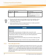
Страница 36: ... 63 core Table 2 1 Environmental Requirements continued Requirement Operating Non Operating The environmental requirements of the blade may be further limited down due to installed accessories such as hard disks or AMC modules with more restrictive environmental requirements Operating temperatures refer to the temperature of the air circulating around the blade and not to the actual component temp...

Страница 37: ...fety extra low voltage SELV circuit A TNV 2 circuit is a circuit whose normal operating voltages exceed the limits for a SELV circuit under normal operating conditions and which is not subject to over voltages from telecommunication networks Table 2 2 Power Requirements Characteristic Value Max power consumption of ATCA 7368 145 W ...

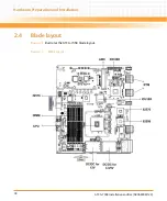
Страница 38: ...Hardware Preparation and Installation ATCA 7368 Installation and Use 6806800M12C 38 2 4 Blade layout Figure 2 1 illustrates the ATCA 7368 blade layout Figure 2 1 Blade Layout ...

Страница 39: ... 5 1 DIMM Memory Modules The blade provides six memory slots for main memory DIMM modules You may install and or remove DIMM memory modules in order to adapt the main memory size to your needs The corresponding installation removal procedures are described in this section The location of the DIMM Memory Modules are shown in Figure Blade Layout on page 38 When installing DIMM memory modules the DIM...

Страница 40: ...s used within one channel must be based on the same memory technology For maximum memory performance all three channels of one CPU must be equipped with an identical amount and size of DIMMs Damage of Circuits Electrostatic discharge and incorrect module installation and removal can damage circuits or shorten their life Before touching the module or electronic components make sure that you are wor...

Страница 41: ...he SRAM has a capacity of up to 16 MB and can be used as persistent memory i e a memory that holds up the contents during reset The flash memory has a capacity of up to 64 MB organized as two memory banks The S F memory module connects to the blade s PCI subsystem It can be configured via an FPGA register The SATA module consists of a Solid State Disc of up to 128 GB and a SATA controller and conn...

Страница 42: ...n the PMEM SATA module to the blade using the two screws that previously had fixed the S F memory module to the blade 4 Reinstall the blade into the system as described in Installing and Removing the Blade on page 44 The additional resource either memory or SATA SSD will be detected automatically during the boot up sequence Damage of Circuits Electrostatic discharge and incorrect module installati...

Страница 43: ...saUSB2 0flashmodulewithacapacityof4GBor16GB Thecorresponding removal installation procedures are described in this section The location of the USB 2 0 Flash Module is shown in Figure Blade Layout on page 38 Damage of Circuits Electrostatic discharge and incorrect module installation and removal can damage circuits or shorten their life Before touching the module or electronic components make sure ...

Страница 44: ...eft side of the flash module 3 Lift the flash module from the socket Installation Procedure To install a USB flash module proceed as follows 1 Remove blade from system as described in Removing the Blade on page 48 2 Insert new flash module in socket 3 Tighten the screw on the left side of the flash module 2 6 Installing and Removing the Blade The blade is fully compatible to the AdvancedTCA standa...

Страница 45: ... shelf proceed as follows Damage of Circuits Electrostatic discharge and incorrect blade installation and removal can damage circuits or shorten their life Before touching the blade or electronic components make sure that you are working in an ESD safe environment Blade Malfunctioning Incorrect blade installation and removal can result in blade malfunctioning When plugging the blade in or removing...

Страница 46: ...top and bottom ejector handles are in the outward position by squeezing the lever and the latch together 2 Insert blade into the shelf by placing the top and bottom edges of the blade in the card guides of the shelf Ensure that the guiding module of shelf and blade are aligned properly 3 Apply equal and steady pressure to the blade to carefully slide the blade into the shelf until you feel resista...

Страница 47: ...completely installed the blue LED starts to blink This indicates that the blade announces its presence to the shelf management controller 6 Wait until the blue LED is switched off then tighten the faceplate screws which secure the blade to the shelf The switched off blue LED indicates that the blade s payload has been powered up and that the blade is active 7 Connect cables to the faceplate if app...

Страница 48: ...faceplate Do not rotate the handle fully outward The blue LED blinks indicating that the blade power down process is ongoing 2 Wait until the blue LED is illuminated permanently then unlatch the upper handle and rotate both handles fully outward Damage of Circuits Electrostatic discharge and incorrect blade installation and removal can damage circuits or shorten their life Before touching the blad...

Страница 49: ...ceplate cables if applicable 4 Unfasten the screws of the faceplate until the blade is detached from the shelf 5 Remove the blade from the shelf Data Loss Removing the blade with the blue LED still blinking causes data loss Wait until the blue LED is permanently illuminated before removing the blade ...

Страница 50: ...Hardware Preparation and Installation ATCA 7368 Installation and Use 6806800M12C 50 ...

Страница 51: ...The blade design provides the possibility to cover unused Faceplate elements like LEDs or push buttons behind a custom overlay foil The following figure gives an overview of the ATCA 7368 faceplate features 3 2 1 LEDs and Interfaces The blade s faceplate provides the following interfaces and control elements Two USB 2 0 ports Serial console port to connect to either payload or IPMC serial I F Out ...

Страница 52: ...Controls Indicators and Connectors ATCA 7368 Installation and Use 6806800M12C 52 Two Ethernet ports Recessed reset button Figure 3 2 Faceplate LEDs ...

Страница 53: ...r Yellow In Service Red green yellow controlled by IPMC This LED is controlled by higher layer software such as middleware or applications Off after power up and lamp test finished Attention ATCA LED3 Amber Attention Amber This LED is controlled by higher layer software such as middleware or applications Off after power up and lamp test finished Ethernet Status LEDs Green Yellow The Ethernet conne...

Страница 54: ...e During blade installation Blue Onboard IPMC powers up Blue blinking Blade is communicating with the shelf manager Off Blade is active During blade removal Blue blinking Blade is notifying the shelf manager that it is going to deactivate Blue Blade is ready to be extracted Table 3 1 Faceplate LEDs continued Indicator Color Description Table 3 2 RJ45 female Serial Line Connector Pinout Pin Signal ...

Страница 55: ...ATCA 7368 Installation and Use 6806800M12C 55 Table 3 3 USB Connector Pinout Pin Signal 1 VP5_USB 2 USB_x_D 3 USB_x_D 4 GND Table 3 4 10 100 1000Base T Fast Ethernet Connector Pinout Pin Signal 1 ETH_TX 2 ETH_TX 3 ETH_RX 4 5 6 ETH_RX 7 8 ...

Страница 56: ...10R is connected to the onboard USB Flash Disk Module 3 3 2 Backplane Connectors Figure 3 3 USB2 0 Flash Disk module connector pinout Table 3 5 Zone 1 Connector P1 Pin Assignment Contact Number Destination Description 1 4 Reserved Reserved 5 IPMC ISC PC0 Hardware Address Bit 0 6 IPMC ISC PC1 Hardware Address Bit 1 7 IPMC ISC PC2 Hardware Address Bit 2 ...

Страница 57: ...6 Logic Ground Logic Ground 27 Power Building Block Enable B 28 Power Building Block Voltage Return A 29 Power Building Block Voltage Return B 30 Power Building Block Early 48V A 31 Power Building Block Early 48V B 32 Power Building Block Enable A 33 Power Building Block 48V A 34 Power Building Block 48V A Table 3 5 Zone 1 Connector P1 Pin Assignment Contact Number Destination Description Table 3 ...

Страница 58: ...ne COM 0 from Glue Logic FPGA RST Button RTM Faceplate USB Serial ATA 4 x PCIexpress X4 and one x2 lane width each with individual clock IPMB L Debugging Management Power 3 3V Payload Power 12V 3 Fabric Channel 1 F1 2 _ TX F1 2 _ TX F1 2 _ RX F1 2 _ RX F1 3 _ TX F1 3 _ TX F1 3 _ RX F1 3 _ RX 4 F1 0 _ TX F1 0 _ TX F1 0 _ RX F1 0 _ RX F1 1 _ TX F1 1 _ TX F1 1 _ RX F1 1 _ RX 5 Base Channel 1 BI1_D A ...

Страница 59: ...lect boot flash as device to boot from This is done via an IPMI command For further details refer to section Supported IPMI Commands on page 95 The BIOS used on the blade is based on the AMI UEFI BIOS with several Emerson extensions integrated Its main features are Initialize CPU chipset and memory Initialize PCI devices Setup utility for setting configuration data IPMC support Serial console redi...

Страница 60: ...blade firmware provides a serial console redirection feature allowing remote access to the blade through a terminal connected to the blade s serial interface The terminal can be connected to display VGA text information Terminal keyboard input is redirected and treated as a normal PC keyboard input The serial console redirection feature can be configured via a setup utility The BIOS contains onlin...

Страница 61: ... modified as follows 4 2 2 Default Access Parameters By default the blade can be accessed using the serial interface COM1 This interface is using a RJ 45 connector at the blade s Faceplate A NULL Modem cable is available as accessory kit for the blade It converts the RJ 45 connector to a standard DSUB connector which can be connected to a remote terminal The following communication parameters are ...

Страница 62: ...eed as follows 1 Configure terminal to communicate using the same parameters as in BIOS setup 2 Connect terminal to NULL modem cable 3 Connect NULL modem cable to COM port of the blade 4 Start up blade 4 3 Changing Configuration Settings When the system is turned on or rebooted the presence and functionality of the system components is tested by POST Power On Self Test ...

Страница 63: ...isplayed on the right side of the menu window 4 4 Boot Options This section describes which boot devices are supported by the BIOS and how to select the boot device Figure 4 1 Main Menu Make sure that BIOS is properly configured prior to installing the operating system and its drivers If you save changes in setup the next time the blade boots BIOS will configure the system according to the setup s...

Страница 64: ...d USB CDROM Removable dev if applicable Attached USB devices of USB external port SAS HDD connected to ARTM SAS Controller Base Ethernet Interface EFI shell In case BIOS does not find any ready bootable device it may loop on the source list until any boot device becomes ready or watchdog bites 4 4 2 Selecting The Boot Device There are two possibilities to determine the device from which BIOS attem...

Страница 65: ...e by selecting another boot device from the boot override list 4 4 4 Network boot Initially the BIOS will contain a classic PXE OPROMs In later project phase if required the BIOS will contain also the UEFI Network Device Driver which allows the loading of executable code from a network server Both DHCP and BOOTP protocols are supported for obtaining an IP address File transmission is accomplished ...

Страница 66: ...user the possibility to select either of the onboard serial port or to disable the console redirection Possible settings enabled disabled The default value is enabled If disabled is selected no redirection of I O to a COM port will be performed COM1 is fully compliant to industry standard 16550 asynchronous communication controllers and is integrated in the Glue Logic FPGA Table 4 2 Network Boot S...

Страница 67: ...s up in to PNE Linux the BBS application will 1 Switch the OOS LED off 2 Switch the IS LED on 3 Switch the ATN LED off When the blade is shutting down gracefully from PNE Linux OS the BBS application will 1 Switch the OOS LED on 2 Switch the IS LED off 3 Switch the ATNLED off 4 7 LED Usage The BIOS uses LEDs U1 U2 and U3 on the front panel to indicate activity of startup progress In boot loader ph...

Страница 68: ...sion BIOS Source boot flash device bank CPU information CPLD information Board Serial Number stored in IPMI FRU data 4 10 USB Ports The USB ports can be disabled by BIOS setup menu 4 11 Supported Operating Systems WRS PNE LE 4 x Linux Red Hat Enterprise Linux 5 x will be supported DOS will be used for debugging Table 4 3 USB Ports USB port BIOS setting Format Options Default Value Onboard USB Flas...

Страница 69: ...vices Software for the ATCA 7368 Programmer s Reference 4 14 BIOS Error Messages In some cases the BIOS prints error messages to the console For example an error message is printed when the CMOS battery is bad or was removed In case of memory errors BIOS disables the defective DIMM module and prints a message similar to the one below and continues Memory Error Detected Disable DIMM 0 Channel 1 Nod...

Страница 70: ...s Table 4 4 Status Code Ranges Status Code Range Description 0x01 0x0F SEC Status Codes Errors 0x10 0x2F PEI execution up to and including memory detection 0x30 0x4F PEI execution after memory detection 0x50 0x5F PEI errors 0x60 0xCF DXE execution up to BDS 0xD0 0xDF DXE errors 0xE0 0xE8 S3 Resume PEI 0xE9 0xEF S3 Resume errors PEI 0xE8 0xEF Memory initialization errors 0xB0 0xBF Additional Memory...

Страница 71: ...h Bridge initialization after microcode loading 0xA OEM initialization after microcode loading 0xB Cache initialization SEC Error Codes 0xC 0xD Reserved for future AMI SEC error codes 0xE Microcode not found 0xF Microcode not loaded Table 4 6 PEI Status Codes Status Code Description Progress Codes 0x10 PEI Core is started 0x15 Pre memory North Bridge initialization is started 0x19 Pre memory South...

Страница 72: ...nitialization codes 0x4F DXE IPL is started Memory Initialization Codes 0xB0 Chipset initialization 0xB1 Detect reset state 0xB2 DIMM detect 0xB3 Clock initialization 0xB4 Read SPD data 0xB5 Early memory controller initialization 0xB6 Check DIMM population 0xB7 Channel initialization 0xB8 Channel training 0xB9 Run Build In Self Test 0xBA Initialize memory map 0xBB Setup RAS configuration 0xBF Memo...

Страница 73: ...pes 0xEE Population error Recovery Progress Codes 0xF0 Recovery condition triggered by firmware Auto recovery 0xF1 Recovery condition triggered by user Forced recovery 0xF2 Recovery process started 0xF3 Recovery firmware image is found 0xF4 Recovery firmware image is loaded 0xF5 0xF7 Reserved for future AMI progress codes Recovery Error Codes 0xF8 Recovery PPI is not available 0xF9 Recovery capsul...

Страница 74: ...arted 0x71 South Bridge DXE SMM initialization is started 0x72 South Bridge devices initialization 0x78 ACPI module initialization 0x79 CSM initialization 0x90 Boot Device Selection BDS phase is started 0x91 Driver connecting is started 0x92 PCI Bus initialization is started 0x93 PCI Bus Hot Plug Controller Initialization 0x94 PCI Bus Enumeration 0x95 PCI Bus Request Resources 0x96 PCI Bus Assign ...

Страница 75: ...untime Set Virtual Address MAP Begin 0xB1 Runtime Set Virtual Address MAP End 0xB2 Legacy Option ROM Initialization 0xB3 System Reset 0xB4 USB hot plug 0xB5 PCI bus hot plug 0xB6 Clean up of NVRAM 0xB7 Configuration Reset reset of NVRAM settings DXE Error Codes 0xD0 CPU initialization error 0xD1 North Bridge initialization error 0xD2 South Bridge initialization error 0xD3 Some of the Architectural...

Страница 76: ...evices are found 0xD7 No Console Input Devices are found 0xD8 Invalid password 0xD9 Error loading Boot Option LoadImage returned error 0xDA Boot Option is failed StartImage returned error 0xDB Flash update is failed 0xDC Reset protocol is not available Table 4 7 DXE Status Codes continued Status Code Description ...

Страница 77: ...and Use 6806800M12C 77 Functional Description 5 1 Overview This chapter describes the specifications and functions of the ATCA 7368 blade 5 2 Block Diagram Figure 5 1 shows the block diagram of ATCA 7368 blade Figure 5 1 Block Diagram ...

Страница 78: ...nt to point links capable of up to 6 4GT S 12MB of shared Last Level cache L3 and an Integrated Memory Controller IMC The processor support all the existing Streaming SIMD Extensions 2 SSE2 Streaming SIMD Extensions 3 SSE3 and Streaming SIMD Extensions 4 SSE4 The processor supports several Advanced Technologies Execute Disable Bit Intel 64 Technology Enhanced Intel SpeedStep Technology Intel Virtu...

Страница 79: ...rconnect links 5 86GT s in each direction Multi core support 6 core per processor Integrated memory controller supporting DDR3 Memory speed 800 1066 1333MHz Package 1366 balls FC BGA TDP 60W 5 4 Memory 5 4 1 DDR3 Main Memory ATCA 7368 provides a single Westmere EP CPU with Integrated Memory Controller IMC IMC supports three independent 72 bit 64 bit Data 8 bit ECC wide DDR3 memory channels ATCA 73...

Страница 80: ...ESI is similar to an x4 PCI express interface The following figure gives an overview of the Xeon 5520 Tylersburg IOH36 D features 5 6 I O Controller The ICH10R provides extensive I O interface support and the boot path to SPI Boot Flash devices for the processor ICH10R is connected to the system through the Enterprise Southbridge Interface ESI of the Xeon 5520 chipset The following is a list of th...

Страница 81: ... System TCO total cost of ownership reduction circuits SMBus interface Two stage Watchdog timer PCI 2 3 interface 32 bit 33 MHz General purpose I O pins The following figure shows the I O functions provided by ICH10R and those used on ATCA 7368 Figure 5 3 ICH10R Diagram ...

Страница 82: ...ration pins to use the FLASH as two 32 Mb mirrored banks switchable only one visible or as continuous 64 MB Flash bank Additionally each bank is write protect able 5 8 Ethernet Ports The blade utilizes various Ethernet controllers that serve the ATCA Base I F Fabric I F Update Channel and Ethernet console All Ethernet interfaces have 1GbE capability except for the Fabric I F controller which can o...

Страница 83: ...ontrol The IPMC serves as the gateway for management applications to access the payload hardware The IPMC firmware FW is stored in two independent memory images Crisis recovery control is provided to allow reboot of the IPMC from a second image if the upgraded FW image is corrupted FW images can be upgraded via HPM 1 IPMI using either IPMB or KCS interface The IPMC supports the initiation of a gra...

Страница 84: ...et button The FRU information of the various modules including front board RTM and other modules can be read via the IPMC and if necessary upgraded through the IPMC The IPMC features Serial over LAN SOL for the payload CPU serial console The SOL interface is available via the ATCA Base I F SOL is activated by specific IPMI commands 5 11 Serial Redirection The CPU serial redirection reroutes the co...

Страница 85: ... to the serial redirection over the sideband interface Client software like openIPMI is required to enable SOL and to communicate with the SOL based serial console 5 13 IPMI Over LAN IPMI messages can be transferred over LAN Base interface using the RMCP protocol as defined in the IPMI v1 5 specification or using the RMCP protocol extension as defined in the IPMI v2 0 specification The RMCP RMCP p...

Страница 86: ...erance of 20 PPM The RTC is fully compliant with DS1287 MC14618 PC87911 and Y2K and provides 256 bytes of backed up CMOS RAM of which 14 bytes containing the RTC time and date information and RTC configuration During power down the RTC consumes0 9uA hr Theoptionalpower downbackupmethodusesaSuperCAPwitha1Farad capacity This provides 300 hours of RTC SRAM backup The default battery is an external 3V...

Страница 87: ...y adding appropriate cards This can be straight forward storage and network interface solutions or local storage hosted on an AMC However it is also necessary to address applications requiring intelligent solutions that can handle tasks like TCP IP off load IPv4 and IPv6 stacks unicast multicast routing acceleration IPSEC acceleration firewall SRTP offload transport protocols and mobile IP among o...

Страница 88: ...Functional Description ATCA 7368 Installation and Use 6806800M12C 88 ...

Страница 89: ... base interface The sideband interface of the Intel 82576 in pass through mode is used to transmit receive its terminal characters via the base interface You can configure the SOL parameters using the standard IPMI commands or via an open source tool called ipmitool 6 2 Installing the ipmitool You can download the open source tool ipmitool from http ipmitool sourceforge net at the time of publishi...

Страница 90: ...L Parameters You can configure the following SOL parameters You can use standard IPMI commands or the ipmitool to modify the parameters 6 3 1 Using Standard IPMI Commands This example shows how to set up the SOL configuration parameter with standard IPMI commands Ipmicmd is used on the local IPMC and the IP is configured Table 6 1 SOL Parameters Parameter Description Set LAN Configuration Paramete...

Страница 91: ...ameter Set In Progress Commit ipmicmd k f 0 c 1 5 0 2 smi 0 6 3 2 Using ipmitool The example below shows how to setup a LAN configuration parameter for a potential SOL session with ipmitool for base 1 channel 5 n0s70 ipmitool lan set 5 ipaddr 172 16 0 221 Setting LAN IP Address to 172 16 0 221 n0s70 The following example shows how to query the LAN parameters that are currently in use for a potenti...

Страница 92: ...fault Gateway MAC 00 00 00 00 00 00 RMCP Cipher Suites 1 2 3 3 Cipher Suite Priv Max Not Available root localhost ipmitool lan print 6 Set in Progress Set Complete Auth Type Support Auth Type Enable Callback User Operator Admin OEM IP Address Source Unspecified IP Address 172 17 1 220 Subnet Mask 255 255 0 0 MAC Address 00 00 00 00 00 00 Default Gateway IP 172 17 0 1 Default Gateway MAC 00 00 00 0...

Страница 93: ...re fulfilled 2 Compile and install the ipmitool on your target which is destined for opening the SOL session on the ATCA 7368 For details refer to Installing the ipmitool on page 89 3 Apply an IP address to the ATCA 7368 SOL interface For details refer to Configuring SOL Parameters on page 90 4 If necessary change user and password Default user is soluser and password is solpasswd 5 Configure the ...

Страница 94: ... 7368 SOL interface ipmitool C 1 I lanplus H 172 16 0 221 U soluser P solpasswd k gkey sol activate For details on the command parameters refer to the ipmitool documentation available on http ipmitool sourceforge net To access BIOS setup screen it is necessary to reset the payload SOL session is only available if the payload is powered on and initialized by the BIOS ...

Страница 95: ...ce v 1 5 This section provides information about the supported IPMI commands 7 2 1 Global IPMI Commands The IPMC supports the following global IPMI commands Table 7 1 Supported Global IPMI Commands Command NetFn Request Response CMD Comments Get Device ID 0x06 0x07 0x01 Cold Reset 0x06 0x07 0x02 Warm Reset 0x06 0x07 0x03 Get Self Test Results 0x06 0x07 0x04 Get Device GUID 0x06 0x07 0x08 Master Wr...

Страница 96: ...nterface Commands Command NetFn Request Response CMD Set BMC Global Enables 0x06 0x07 0x2E Get BMC Global Enables 0x06 0x07 0x2F Clear Message Flags 0x06 0x07 0x30 Get Message Flags 0x06 0x07 0x31 Get Message 0x06 0x07 0x33 Send Message 0x06 0x07 0x34 Set Channel Access 0x06 0x07 0x40 Get Channel Access 0x06 0x07 0x41 Get Channel Info 0x06 0x07 0x42 Set User Access 0x06 0x07 0x43 Get User Access 0...

Страница 97: ... NetFn Request Response CMD Reset Watchdog Timer 0x06 0x07 0x22 Set Watchdog Timer 0x06 0x07 0x24 Get Watchdog Timer 0x06 0x07 0x25 Table 7 4 Supported SEL Device Commands Command NetFn Request Response CMD Get SEL Info 0x0A 0x0B 0x40 Reserve SEL 0x0A 0x0B 0x42 Get SEL Entry 0x0A 0x0B 0x43 Add SEL Entry 0x0A 0x0B 0x44 Clear SEL 0x0A 0x0B 0x47 Get SEL Time 0x0A 0x0B 0x48 Set SEL Time 0x0A 0x0B 0x49...

Страница 98: ...Comments Get Device SDR Info 0x04 0x05 0x20 Get Device SDR 0x04 0x05 0x21 Reserve Device SDR Repository 0x04 0x05 0x22 Get Sensor Reading Factors 0x04 0x05 0x23 Set Sensor Hysteresis 0x04 0x05 0x24 Get Sensor Hysteresis 0x04 0x05 0x25 Set Sensor Threshold 0x04 0x05 0x26 Most of the threshold based sensors have fixed thresholds Before using this command check whether threshold setting is supported ...

Страница 99: ...tion The boot parameters 96 to 127 are OEM specific which can be used for different purposes When using the Get Set System Boot Options commands except for parameter 100 use the response request data fields with the Set Selector and the Block Selector set to 0x00 When using the Get Set System Boot Option for the parameter 100 the Set Selector and the Block Selector have a specific meaning Details ...

Страница 100: ...e the on board FPGA loads its configuration stream from 96 POST Type 97 Timeout for graceful shutdown 98 BIOS boot parameters as defined in Table 7 15 on page 106 100 Table 7 9 System Boot Options Parameter 96 Data Byte Description 1 Bits 7 1 Reserved Bit 0 Default backup boot flash selection 0 Boot from default boot flash 1 Boot from backup boot flash Note the newly selected boot flash is connect...

Страница 101: ...System Boot Options Parameter 97 Data Byte Description 1 POST Type Data 1 Set Selector This is the processor ID for which the boot option is to be set 2 Data 2 POST Type Selector This parameter is used to specify the POST type that the IPMC will execute 0x00 Short POST 0x01 Long POST 0x02 to 0xFF Not used The System Boot Options parameter 97 is non volatile During blade production its data is init...

Страница 102: ...eters and executes the boot process accordingly Note that the boot parameters in the IPMC storage area have higher priority than the same boot options which may be configured in the firmware itself for example using the setup menu The storage area is divided into two parts the default area and the user area The user area can be read and written by an IPMI user and by default is the area which the ...

Страница 103: ...hen setting or reading the System Boot Options parameter 100 On some blades with particular firmware types changing a boot parameter in the firmware setup menu changes the boot parameter in the user area as well if the same parameter is defined both in the user area and the set up menu Details are given below Figure 7 1 System Boot Options Parameter 100 Information Flow Overview Table 7 12 System ...

Страница 104: ...m over the boot parameters data section LSB first For backward compatibility reasons the checksums 0x0000 and 0xFFFF are accepted as valid They indicate that no checksum has been calculated and stored Table 7 13 System Boot Options Parameter 100 SET Command Usage Byte Description Request Data 1 Bit 7 when set to 1 the storage area on the IPMC is locked i e no other software can access it This shou...

Страница 105: ...ns Parameter 100 GET Command Usage Byte Description Request Data 1 Bit 7 reserved Set to 0 Bits 6 0 must contain the value 100 indicating this OEM system boot option 2 Set Selector 0 User area 1 Default area 3 Block Selector Zero based index of the 16 byte block which you want to read from Index 0 refers to the first block of 16 bytes which includes the first two bytes which indicate the boot para...

Страница 106: ... area can be easily determined by the number of previously performed successful read accesses This is supported by HPI for details refer to the System Management Interface Based on HPI B User s Guide related to your system environment When used in the System Boot Options parameter 100 the boot parameters and their values are case sensitive All boot options listed in the following table are set by ...

Страница 107: ..._interleave auto 6 4 3 2 1 auto rank_interleave auto 4 2 1 auto hw_mem_test on off on patrol_scrub on off on demand_scrub on off off all_usb_device on off on usb_2 0_cont_mode on off on usb fp_on fp_off fp_on rtm_on rtm_off rtm_on onboard_on onboard_off onboard_on usb_boot on off on sata_mode off ide ahci raid ide sata_cont_0 off enhc cmpt cmpt sata_cont_1 off enhc cmpt enhc ehci_hand_off on off o...

Страница 108: ...off 1 2 3 5 7 10 15 20 5 nothing reset pwdw pwcy reset bios_watchdog on off on 3 4 5 6 3 reset reset log_status_code off both errcode prgcode both frontnet_boot on off off basenet_boot on off on fabricnet_boot on off off artm_net_boot on off off artm_sas_boot on off on ssc_support on off on wait_rtm_time numeric 0 255 0 wait_rtm_policy force auto auto setup_timeout numeric 0 65535 4 number_lock on...

Страница 109: ...6 boot_order Devices Device Description sata0 SATA device 0 Debug SATA sata1 SATA device 1 RTM Debug SATA sata5 SATA device 5 Onboard SATA sataonboard SATA device 5 Onboard SATA sashdd SAS HDD mounted on the RTM sas0_nn SAS Controller nn SCSI ID use this when a SAS array is connected to the RTM frontnet Front Panel Network basenet0 Base0 Network basenet1 Base1 Network usb1 USB frontpanel 1 usb2 US...

Страница 110: ...devices are supported Example boot_order sas0_03 basenet0 usbkey sata1 Table 7 16 boot_order Devices continued Device Description Table 7 17 Supported LAN Device Commands Command NetFn Request Response CMD Set LAN Configuration Parameters 0x0C 0x0D 0x01 Get LAN Configuration Parameters 0x0C 0x0D 0x02 Set SOL Configuration Parameters 0x0C 0x0D 0x21 Get SOL Configuration Parameters 0x0C 0x0D 0x22 ...

Страница 111: ...D 0x04 Get FRU LED Properties 0x2C 0x2D 0x05 Get FRU LED Color Capabilities 0x2C 0x2D 0x06 Set FRU LED State 0x2C 0x2D 0x07 Get FRU LED State 0x2C 0x2D 0x08 Set IPMB State 0x2C 0x2D 0x09 Set FRU Activation Policy 0x2C 0x2D 0x0A Get FRU Activation Policy 0x2C 0x2D 0x0B Set FRU Activation 0x2C 0x2D 0x0C Get Device Locator Record ID 0x2C 0x2D 0x0D The Emerson IPMCs support the standard PICMG 3 0 and ...

Страница 112: ...re block 0x2C 0x2D 0x32 Finish firmware upload 0x2C 0x2D 0x33 Get upgrade status 0x2C 0x2D 0x34 Activate firmware 0x2C 0x2D 0x35 Query self test results 0x2C 0x2D 0x36 Query rollback status 0x2C 0x2D 0x37 Initiate manual rollback 0x2C 0x2D 0x38 Table 7 18 Supported PICMG 3 0 Commands continued Command NetFn Request Response CMD Comments The firmware upgrade commands supported by the blade are impl...

Страница 113: ...efore sending any of these commands the shelf management software must check whether the receiving IPMI controller supports Emerson specific IPMI commands by using the IPMI command Get Device ID Sending Emerson specific commands to IPMI controllers which do not support these IPMI commands will lead to no or undefined results Proper handling of these commands is required to write a portable applica...

Страница 114: ...ee Table 2 16 Feature Selector Assignments 5 Feature Configuration 00h disabled Feature Selector E2h 01h enabled Feature Selector E2h Default 02h FFh reserved 6 Persistency Duration 00h volatile Actual duration depends on implementation 01h FFh reserved Response Data 1 Completion Code Generic plus the following command specific completion codes 80h feature selector not supported 81h feature config...

Страница 115: ... Number A value of CDh shall be used 2 2nd byte of Emerson IANA Enterprise Number A value of 65h shall be used 3 MSB of Emerson IANA Enterprise Number A value of 00h shall be used 4 Feature Selector for details see Table 7 23 on page 116 Response Data 1 Completion Code Generic plus the following command specific completion codes 80h feature selector not supported 2 LSB of Emerson IANA Enterprise N...

Страница 116: ...escription E2h Boot Firmware Automatic Switchover Function Enable Disable Table 7 24 Serial Output Commands Command Name NetFn Request Response CMD Description Set Serial Output 0x2E 0x2F 0x15 See Set Serial Output Command on page 116 Get Serial Output 0x2E 0x2F 0x16 See Get Serial Output Command on page 117 Table 7 25 Request Data of Set Serial Output Command Byte Data Field 1 LSB of Emerson IANA...

Страница 117: ...ector All other values are reserved Note Only the faceplate connector is supported No connector on the RTM available 5 Serial connector instance number A sequential number that starts from 0 6 Serial output selector 0 BIOS 2 IPMC debug console All other values are reserved Table 7 25 Request Data of Set Serial Output Command continued Byte Data Field Table 7 26 Response Data of Set Serial Output C...

Страница 118: ...cond byte of Emerson IANA Enterprise number A value of 0x65 has to be used 3 MSB of Emerson IANA Enterprise number A value of 0x00 has to be used 4 Serial connector type 0 faceplate connector 1 Backplane connector All other values are reserved Note Only the faceplate connector is supported No connector on the RTM available 5 Serial connector instance number A sequential number that starts from 0 T...

Страница 119: ...rdware Address Table 7 37 on page 127 0x2E 0x2F 0x06 Get Handle Switch Table 7 38 on page 128 0x2E 0x2F 0x07 Set Handle Switch Table 7 39 on page 129 0x2E 0x2F 0x08 Get Payload Communication Time Out Table 7 40 on page 129 0x2E 0x2F 0x09 Set Payload Communication Time Out Table 7 41 on page 130 0x2E 0x2F 0x0A Enable Payload Control Table 7 42 on page 131 0x2E 0x2F 0x0B Disable Payload Control Tabl...

Страница 120: ...or debugging purposes and or operation in a non ATCA environment In standalone mode the carrier IPMC automatically activates and deactivates the on carrier payload and modules whenever it does not violate any carrier limitations Manual standalone Manual standalone mode is equivalent to standalone mode with only one exception carrier IPMC control over the on carrier payload is automatically disable...

Страница 121: ...cts a threshold crossing Bits 2 1 Mode The current IPMC modes are defined as 0 Normal 1 Standalone for a description refer to Table 7 30 2 Manual Standalone for a description refer to Table 7 30 Bit 0 Control If set to 0 the IPMC control over the payload is disabled 6 Bits 4 7 Metallic Bus 2 Events These bits indicate pending Metallic Bus 2 requests arrived from the shelf manager 0 Metallic Bus 2 ...

Страница 122: ...s 0 3 Clock Bus 1 Events These bits indicate pending Clock Bus 1 requests arrived from the shelf manager 0 Clock Bus 1 Query 1 Clock Bus 1 Release 2 Clock Bus 1 Force 3 Clock Bus 1 Free 8 Bits 4 7 Reserved Bits 0 3 Clock Bus 3 Events These bits indicate pending Clock Bus 3 requests arrived from the shelf manager 0 Clock Bus 3 Query 1 Clock Bus 3 Release 2 Clock Bus 3 Force 3 Clock Bus 3 Free Table...

Страница 123: ...prise ID 0x00400A 16394 Pigeon Point Systems LSB Byte first byte 1 0A byte 2 40 byte 3 00 4 Interface ID 0 Serial Debug Interface Response Data 1 Completion Code 2 4 PPS IANA Private Enterprise ID 0x00400A 16394 Pigeon Point Systems LSB Byte first byte 2 0A byte 3 40 byte 4 00 5 Bit 7 Echo On If this bit is set the IPMC enables echo for the given serial interface Bits 6 4 Reserved Bits 3 0 Baud Ra...

Страница 124: ...prise ID 0x00400A 16394 Pigeon Point Systems LSB Byte first byte 1 0A byte 2 40 byte 3 00 4 Interface ID 0 Serial Debug Interface 5 Bit 7 Echo On If this bit is set the IPMC enables echo for the given serial interface Bits 6 4 Reserved Bits 3 0 Baud Rate ID The baud rate ID defines the interface baud rate as follows 0 9600 bps 1 19200 bps 2 38400 bps 3 57600 bps unsupported 4 115200 bps unsupporte...

Страница 125: ...p Enable If set to 1 the IPMC provides a trace of IPMB L messages that are arriving to going from the IPMC via IPMB L Bit 6 n a Bit 5 KCS Dump Enable Ifsetto 1 theIPMCprovidesatraceofKCSmessagesthat are arriving to going from the IPMC via KCS Bit 4 IPMB Dump Enable If set to 1 the IPMC provides a trace of IPMB messages that are arriving to going from the IPMC via IPMB O Bit 3 n a Bit 2 Alert Loggi...

Страница 126: ...set to 1 the IPMC provides a trace of KCS messages that are arriving to going from the IPMC via KCS Bit 4 IPMB Dump Enable If set to 1 the IPMC provides a trace of IPMB messages that are arriving to going from the IPMC via IPMB O Bit 3 n a Bit 2 Alert Logging Enable If set to 1 the IPMC outputs important alert messages onto the serial debug interface Bit 1 Low level Error Logging Enable If set to ...

Страница 127: ...est Data 1 3 PPS IANA Private Enterprise ID 0x00400A 16394 Pigeon Point Systems LSB Byte first byte 1 0A byte 2 40 byte 3 00 Response Data 1 Completion Code 2 4 PPS IANA Private Enterprise ID 0x00400A 16394 Pigeon Point Systems LSB Byte first byte 2 0A byte 3 40 byte 4 00 5 Hardware Address Table 7 37 Set Hardware Address Command Description Type Byte Data Field Request Data 1 3 PPS IANA Private E...

Страница 128: ... 2 0A byte 3 40 byte 4 00 Table 7 37 Set Hardware Address Command Description continued Type Byte Data Field Table 7 38 Get Handle Switch Command Description Type Byte Data Field Request Data 1 3 PPS IANA Private Enterprise ID 0x00400A 16394 Pigeon Point Systems LSB Byte first byte 1 0A byte 2 40 byte 3 00 4 FRU ID specify as 0 Response Data 1 Completion Code 2 4 PPS IANA Private Enterprise ID 0x0...

Страница 129: ...1 3 PPS IANA Private Enterprise ID 0x00400A 16394 Pigeon Point Systems LSB Byte first byte 1 0A byte 2 40 byte 3 00 4 FRU ID specify as 0 5 Handle Switch Status 0x00 The handle switch is open 0x01 The handle switch is closed 0x02 The handle switch state is read from hardware Response Data 1 Completion Code 2 4 PPS IANA Private Enterprise ID 0x00400A 16394 Pigeon Point Systems LSB Byte first byte 2...

Страница 130: ...t may vary from 0 1 to 25 5 seconds Table 7 40 Get Payload Communication Time Out Command Description continued Type Byte Data Field Table 7 41 Set Payload Communication Time Out Command Description Type Byte Data Field Request Data 1 3 PPS IANA Private Enterprise ID 0x00400A 16394 Pigeon Point Systems LSB Byte first byte 1 0A byte 2 40 byte 3 00 4 Payload Time out Payload communication time out m...

Страница 131: ...ta 1 3 PPS IANA Private Enterprise ID 0x00400A 16394 Pigeon Point Systems LSB Byte first byte 1 0A byte 2 40 byte 3 00 Response Data 1 Completion Code 2 4 PPS IANA Private Enterprise ID 0x00400A 16394 Pigeon Point Systems LSB Byte first byte 2 0A byte 3 40 byte 4 00 Table 7 43 Disable Payload Control Command Description Type Byte Data Field Request Data 1 3 PPS IANA Private Enterprise ID 0x00400A ...

Страница 132: ...B Byte first byte 1 0A byte 2 40 byte 3 00 4 Reset Type Code 0x00 Cold IPMC reset to the current mode 0x01 Cold IPMC reset to the Normal mode 0x02 Cold IPMC reset to the Standalone mode for a description refer to Table 7 30 0x03 ColdIPMCresettotheManualStandalonemode for a description refer to Table 7 30 0x04 Reset the IPMC and enter Upgrade mode Response Data 1 Completion Code 2 4 PPS IANA Privat...

Страница 133: ... upon receiving the Graceful Reset command or time out If the IPMC participation is necessary the payload must request the IPMC to perform a payload reset The Graceful Reset command is also used to notify the IPMC about the completion of the payload shutdown sequence 2 4 PPS IANA Private Enterprise ID 0x00400A 16394 Pigeon Point Systems LSB Byte first byte 2 0A byte 3 40 byte 4 00 Table 7 45 Hang ...

Страница 134: ... payload Interface to notify the IPMC that the payload shutdown is complete To avoid deadlocks that may occur if the payload software does not respond the IPMC provides a special time out for the payload shutdown sequence If the payload does not send the Graceful Reset command within a definite period of time the IPMC assumes that the payload shutdown sequence is finished and resets the payload Ta...

Страница 135: ...rise ID 0x00400A 16394 Pigeon Point Systems LSB Byte first byte 1 0A byte 2 40 byte 3 00 4 5 Time Out measured in hundreds of milliseconds LSB first Response Data 1 Completion Code 2 4 PPS IANA Private Enterprise ID 0x00400A 16394 Pigeon Point Systems LSB Byte first byte 2 0A byte 3 40 byte 4 00 Table 7 49 Get Module State Command Description Type Byte Data Field Request Data 1 3 PPS IANA Private ...

Страница 136: ... is disabled 1 Management power is enabled Bit 3 0 Management power is bad 1 Management power is good Bit 4 0 Payload power is disabled 1 Payload power is enabled Bit 5 0 Payload power is bad 1 Payload power is good Bit 6 0 IPMB L buffer is not attached 1 IPMB L buffer is attached Bit 7 0 IPMB L buffer is not ready 1 IPMB L buffer is ready Table 7 49 Get Module State Command Description continued ...

Страница 137: ...equest Data 1 3 PPS IANA Private Enterprise ID 0x00400A 16394 Pigeon Point Systems LSB Byte first byte 1 0A byte 2 40 byte 3 00 4 Module Site ID Response Data 1 Completion Code 2 4 PPS IANA Private Enterprise ID 0x00400A 16394 Pigeon Point Systems LSB Byte first byte 1 0A byte 2 40 byte 3 00 Table 7 51 Disable Module Site Command Description Type Byte Data Field Request Data 1 3 PPS IANA Private E...

Страница 138: ... the carrier SDR repository Table 7 52 Reset Carrier SDR Repository Command Description Type Byte Data Field Request Data 1 3 PPS IANA Private Enterprise ID 0x00400A 16394 Pigeon Point Systems LSB Byte first byte 1 0A byte 2 40 byte 3 00 Response Data 1 Completion Code 2 4 PPS IANA Private Enterprise ID 0x00400A 16394 Pigeon Point Systems LSB Byte first byte 2 0A byte 3 40 byte 4 00 ...

Страница 139: ...cess Internal use area Not used Board info area Mfg date time According to Platform Management FRU information Storage Definition v1 0 r Board manufacturer EMERSON r Board product name Product name of the specific blade variant r Board serial number Defined by manufacture r Board part number Product name of the specific blade variant r Product info area Product manufacturer EMERSON r Product name ...

Страница 140: ...bed in the section E Keying r Carrier Information table record PICMG record ID 0x1A r Carrier activation and current management record PICMG record ID 0x17 r Carrier point to point connectivity records PICMG record ID 0x18 r AMC point to point connectivity PICMG record ID 0x19 r SW and FW Version Information Record OEM r CPU Information Record OEM r Table 8 1 FRU information continued Area Descrip...

Страница 141: ... NOT SET 3 NOT SET 0x01 1 3 0 1 FabricInterface 1 0 SET 1 SET 2 SET 3 SET 0x02 1 4 0 1 FabricInterface 1 0 SET 1 NOT SET 2 NOT SET 3 NOT SET 0x02 0 5 0 1 FabricInterface 2 0 SET 1 SET 2 SET 3 SET 0x02 1 6 0 1 FabricInterface 2 0 SET 1 NOT SET 2 NOT SET 3 NOT SET 0x02 0 Table 8 3 Power Configuration Item Value Description Dynamic power reconfiguration support No While the blade is powered it suppor...

Страница 142: ...c 0s Table 8 3 Power Configuration continued Item Value Description Table 8 4 Sensor Data Records Sensor Name Sensor Type Sensor Number Detailed SDR Description HS Carrier Hot Swap 0xF0 0x00 See Table 8 5 on page 146 HS AMC Hot Swap 0xF0 0x01 See Table 8 6 on page 147 HS RTM Hot Swap 0xF0 0x02 See Table 8 7 on page 148 48V A Volts Voltage 0x2 0x03 See Table 8 8 on page 149 48V B Volts Voltage 0x2 ...

Страница 143: ...n page 171 DDR 6 Temp Temperature 0x01 0x12 See Table 8 23 on page 172 12 0V Voltage 0x02 0x13 See Table 8 24 on page 174 3 3V Voltage 0x02 0x14 See Table 8 25 on page 175 3 3V Mgmt Voltage 0x02 0x15 See Table 8 26 on page 176 1 8V Eth Voltage 0x02 0x16 See Table 8 27 on page 178 1 5V Voltage 0x02 0x17 See Table 8 28 on page 179 1 2V Voltage 0x02 0x18 See Table 8 29 on page 180 VCC CPU Voltage 0x0...

Страница 144: ...Boot Initiated 0x1D 0x22 See Table 8 39 on page 192 POST Code OEM 0xD2 0x23 See Table 8 40 on page 193 IPMC Status OEM 0xD5 0x24 See Table 8 41 on page 194 Power Good Entity Presence 0x25 0x25 See Table 8 42 on page 195 Boot Bank OEM 0xD2 0x26 See Table 8 43 on page 196 Reset Source OEM 0xD2 0x27 See Table 8 44 on page 197 CPU Status Processor 0x07 0x28 See Table 8 45 on page 198 Table 8 4 Sensor ...

Страница 145: ... Information and SDR Summary ATCA 7368 Installation and Use 6806800M12C 145 The following figure shows the locations of all temperature sensors available on board Figure 8 1 Location of Temperature Sensors ...

Страница 146: ...ing Type 0x6F Discrete sensor specific Assertion Event Mask Byte 15 0xFF Assertion Event Mask Byte 16 0x00 Deassertion Event Mask Byte 17 0x00 Deassertion Event Mask Byte 18 0x00 Threshold Mask Byte 19 0xFF Threshold Mask Byte 20 0x00 Base Unit 0x00 unspecified Rearm mode 0x01 Auto Hysteresis Support 0x00 No Hysteresis or unspecified Threshold Access Support 0x00 No Thresholds Event Message Contro...

Страница 147: ...nt Reading Type 0x6F Sensor specific Assertion Event Mask Byte 15 0xFF Assertion Event Mask Byte 16 0x00 Deassertion Event Mask Byte 17 0x00 Deassertion Event Mask Byte 18 0x00 Threshold Mask Byte 19 0xFF Threshold Mask Byte 20 0x00 Base Unit 0x00 unspecified Rearm mode 0x01 Auto Hysteresis Support 0x00 No Hysteresis or unspecified Threshold Access Support 0x00 No Thresholds Event Message Control ...

Страница 148: ...nt Reading Type 0x6F Sensor specific Assertion Event Mask Byte 15 0xFF Assertion Event Mask Byte 16 0x00 Deassertion Event Mask Byte 17 0x00 Deassertion Event Mask Byte 18 0x00 Threshold Mask Byte 19 0xFF Threshold Mask Byte 20 0x00 Base Unit 0x00 unspecified Rearm mode 0x01 Auto Hysteresis Support 0x00 No Hysteresis or unspecified Threshold Access Support 0x00 No Thresholds Event Message Control ...

Страница 149: ...sertion Event Mask Byte 15 0x14 Assertion Event Mask Byte 16 0x6A Deassertion Event Mask Byte 17 0x14 Deassertion Event Mask Byte 18 0x6A Threshold Mask Byte 19 0x36 Threshold Mask Byte 20 0x36 Base Unit 0x04 Volts Rearm mode 0x01 Auto Hysteresis Support 0x01 Readable Threshold Access Support 0x02 Readable and settable Event Message Control 0x00 Per Threshold Discrete State Nominal Reading 0x94 48...

Страница 150: ... byte Analog sensor reading Table 8 9 48V B Volts Feature Raw Value Description Sensor Name 48V B Volts Sensor LUN 0x00 Sensor Number 0x04 Entity ID 0x0A Power Supply Sensor Type 0x02 Voltage Event Reading Type 0x01 Threshold Assertion Event Mask Byte 15 0x14 Assertion Event Mask Byte 16 0x6A Deassertion Event Mask Byte 17 0x14 Deassertion Event Mask Byte 18 0x6A Threshold Mask Byte 19 0x36 Thresh...

Страница 151: ...threshold 0xE2 73 45 Upper critical threshold 0xDF 72 475 Upper non critical threshold 0x00 unspecified Lower non recoverable threshold 0x74 37 7 Lower critical threshold 0x78 38 9 Lower non critical threshold 0x00 unspecified Reading Definition Analog reading byte Analog sensor reading Table 8 10 48V Amps Feature Raw Value Description Sensor Name 48V Current Sensor LUN 0x00 Sensor Number 0x05 Ent...

Страница 152: ...Auto Hysteresis Support 0x01 Readable Threshold Access Support 0x02 Readable and settable Event Message Control 0x00 Per Threshold Discrete State Nominal Reading 0x36 5 076 Upper non recoverable threshold 0x48 6 77 Upper critical threshold 0x45 6 49 Upper non critical threshold 0x41 6 11 Lower non recoverable threshold 0x00 unspecified Lower critical threshold 0x00 unspecified Lower non critical t...

Страница 153: ...eshold Assertion Event Mask Byte 15 0x14 Assertion Event Mask Byte 16 0x6A Deassertion Event Mask Byte 17 0x14 Deassertion Event Mask Byte 18 0x6A Threshold Mask Byte 19 0x36 Threshold Mask Byte 20 0x36 Base Unit 0x04 Volts Rearm mode 0x01 Auto Hysteresis Support 0x01 Readable Threshold Access Support 0x02 Readable and settable Event Message Control 0x00 Per Threshold Discrete State Nominal Readin...

Страница 154: ...ng Table 8 12 Input Power Feature Raw Value Description Sensor Name Input Power Sensor LUN 0x00 Sensor Number 0x07 Entity ID 0x0A Power Supply Sensor Type 0x0B Other Units based Sensor Event Reading Type 0x01 Threshold Assertion Event Mask Byte 15 0x80 Assertion Event Mask Byte 16 0x0A Deassertion Event Mask Byte 17 0x80 Deassertion Event Mask Byte 18 0x7A Threshold Mask Byte 19 0x38 Threshold Mas...

Страница 155: ...old 0xC6 241 Upper non critical threshold 0xBD 230 Lower non recoverable threshold 0x00 unspecified Lower critical threshold 0x00 unspecified Lower non critical threshold 0x00 unspecified Reading Definition Analog reading byte Analog sensor reading Table 8 13 PWR Status Feature Raw Value Description Sensor Name PWR Status Sensor LUN 0x00 Sensor Number 0x08 Entity ID 0x0A Power Supply Sensor Type 0...

Страница 156: ...Base Unit 0x00 unspecified Rearm mode 0x01 Auto Hysteresis Support 0x00 No Hysteresis or unspecified Threshold Access Support 0x00 No Thresholds Event Message Control 0x01 Entire Sensor only Reading Definition Table 8 14 Inlet Temp Feature Raw Value Description Sensor Name Inlet Temp Sensor LUN 0x00 Sensor Number 0x09 Entity ID 0xA0 PICMG Front Board Sensor Type 0x01 Temperature Event Reading Type...

Страница 157: ...rm mode 0x01 Auto Hysteresis Support 0x02 Readable and Settable Threshold Access Support 0x02 Readable and Settable Event Message Control 0x00 Per Threshold Discrete State Nominal Reading ATCA7368_0GB 0x1F ATCA7368_0GB_LS 0x1F ATCA7368_0GB_CE 0x1E ATCA7368_0GB_L_CE 0x1E ATCA7368_0GB_LS_CE 0x1E ATCA7368_0GB_LSL_CE 0x1E ATCA7368_0GB 31 ATCA7368_0GB_LS 31 ATCA7368_0GB_CE 30 ATCA7368_0GB_L_CE 30 ATCA7...

Страница 158: ...0GB_LS 0x39 ATCA7368_0GB_CE 0X2D ATCA7368_0GB_L_CE 0X2D ATCA7368_0GB_LS_CE 0x2D ATCA7368_0GB_LSL_CE 0x2D ATCA7368_0GB 57 ATCA7368_0GB_LS 57 ATCA7368_0GB_CE 45 ATCA7368_0GB_L_CE 45 ATCA7368_0GB_LS_CE 45 ATCA7368_0GB_LSL_CE 45 Upper non critical threshold ATCA7368_0GB 0x2C ATCA7368_0GB_LS 0x2C ATCA7368_0GB_CE 0x23 ATCA7368_0GB_L_CE 0x23 ATCA7368_0GB_LS_CE 0x23 ATCA7368_0GB_LSL_CE 0x23 ATCA7368_0GB 4...

Страница 159: ...me Outlet Temp Sensor LUN 0x00 Sensor Number 0x0A Entity ID 0xA0 PICMG Front Board Sensor Type 0x01 Temperature Event Reading Type 0x01 Threshold Assertion Event Mask Byte 15 0x80 Assertion Event Mask Byte 16 0x0A Deassertion Event Mask Byte 17 0x80 Deassertion Event Mask Byte 18 0x7A Threshold Mask Byte 19 0x38 Threshold Mask Byte 20 0x38 Base Unit 0x01 deg C Rearm mode 0x01 Auto Hysteresis Suppo...

Страница 160: ...S_CE 0x23 ATCA7368_0GB_LSL_CE 0x23 ATCA7368_0GB 35 ATCA7368_0GB_LS 35 ATCA7368_0GB_CE 35 ATCA7368_0GB_L_CE 35 ATCA7368_0GB_LS_CE 35 ATCA7368_0GB_LSL_CE 35 Upper non recoverable threshold ATCA7368_0GB 0x50 ATCA7368_0GB_LS 0x50 ATCA7368_0GB_CE 0x46 ATCA7368_0GB_L_CE 0x46 ATCA7368_0GB_LS_CE 0x46 ATCA7368_0GB_LSL_CE 0x46 ATCA7368_0GB 80 ATCA7368_0GB_LS 80 ATCA7368_0GB_CE 70 ATCA7368_0GB_L_CE 70 ATCA73...

Страница 161: ...L_CE 60 Upper non critical threshold ATCA7368_0GB 0x37 ATCA7368_0GB_LS 0x37 ATCA7368_0GB_CE 0x32 ATCA7368_0GB_L_CE 0x32 ATCA7368_0GB_LS_CE 0x32 ATCA7368_0GB_LSL_CE 0x32 ATCA7368_0GB 55 ATCA7368_0GB_LS 55 ATCA7368_0GB_CE 50 ATCA7368_0GB_L_CE 50 ATCA7368_0GB_LS_CE 50 ATCA7368_0GB_LSL_CE 50 Lower non recoverable threshold 0x00 unspecified Lower critical threshold 0x00 unspecified Lower non critical t...

Страница 162: ...sertion Event Mask Byte 15 0x80 Assertion Event Mask Byte 16 0x0A Deassertion Event Mask Byte 17 0x80 Deassertion Event Mask Byte 18 0x7A Threshold Mask Byte 19 0x38 Threshold Mask Byte 20 0x38 Base Unit 0x01 deg C Rearm mode 0x01 Auto Hysteresis Support 0x02 Readable and settable Threshold Access Support 0x02 Readable and settable Event Message Control 0x00 Per Threshold Discrete State Nominal Re...

Страница 163: ...og sensor reading Table 8 17 CPU Temp Feature Raw Value Description Sensor Name CPU Temp Sensor LUN 0x00 Sensor Number 0x0C Entity ID 0xA0 PICMG Front Board Sensor Type 0x01 Temperature Event Reading Type 0x01 Threshold Assertion Event Mask Byte 15 0x80 Assertion Event Mask Byte 16 0x0A Deassertion Event Mask Byte 17 0x80 Deassertion Event Mask Byte 18 0x0A Threshold Mask Byte 19 0x38 Threshold Ma...

Страница 164: ...A7368_0GB_L_CE 0x32 ATCA7368_0GB_LS_CE 0x32 ATCA7368_0GB_LSL_CE 0x32 ATCA7368_0GB 50 ATCA7368_0GB_LS 50 ATCA7368_0GB_CE 50 ATCA7368_0GB_L_CE 50 ATCA7368_0GB_LS_CE 50 ATCA7368_0GB_LSL_CE 50 Upper non recoverable threshold ATCA7368_0GB 0x65 ATCA7368_0GB_LS 0x65 ATCA7368_0GB_CE 0x5E ATCA7368_0GB_L_CE 0x5E ATCA7368_0GB_LS_CE 0x5E ATCA7368_0GB_LSL_CE 0x5E ATCA7368_0GB 101 ATCA7368_0GB LS 101 ATCA7368_0...

Страница 165: ...LSL_CE 84 Upper non critical threshold ATCA7368_0GB 0x46 ATCA7368_0GB_LS 0x46 ATCA7368_0GB_CE 0x4A ATCA7368_0GB_L_CE 0x4A ATCA7368_0GB_LS_CE 0x4A ATCA7368_0GB_LSL_CE 0x4A ATCA7368_0GB 70 ATCA7368_0GB_LS 70 ATCA7368_0GB_CE 74 ATCA7368_0GB_L_CE 74 ATCA7368_0GB_LS_CE 74 ATCA7368_0GB_LSL_CE 74 Lower non recoverable threshold 0x00 unspecified Lower critical threshold 0x00 unspecified Lower non critical...

Страница 166: ...ssertion Event Mask Byte 15 0x80 Assertion Event Mask Byte 16 0x0A Deassertion Event Mask Byte 17 0x80 Deassertion Event Mask Byte 18 0x0A Threshold Mask Byte 19 0x38 Threshold Mask Byte 20 0x38 Base Unit 0x01 deg C Rearm mode 0x01 Auto Hysteresis Support 0x02 Readable and settable Threshold Access Support 0x02 Readable and settable Event Message Control 0x00 Per Threshold Discrete State Nominal R...

Страница 167: ... sensor reading Table 8 19 DDR 2 Temp Feature Raw Value Description Sensor Name DDR 2 Temp Sensor LUN 0x00 Sensor Number 0x0E Entity ID 0xA0 PICMG Front Board Sensor Type 0x01 Temperature Event Reading Type 0x01 Threshold Assertion Event Mask Byte 15 0x80 Assertion Event Mask Byte 16 0x0A Deassertion Event Mask Byte 17 0x80 Deassertion Event Mask Byte 18 0x0A Threshold Mask Byte 19 0x38 Threshold ...

Страница 168: ...itical threshold 0x55 85 Upper non critical threshold 0x4B 75 Lower non recoverable threshold 0x00 unspecified Lower critical threshold 0x00 unspecified Lower non critical threshold 0x00 unspecified Reading Definition Analog reading byte Analog sensor reading Table 8 20 DDR 3 Temp Feature Raw Value Description Sensor Name DDR 3 Temp Sensor LUN 0x00 Sensor Number 0x0F Entity ID 0xA0 PICMG Front Boa...

Страница 169: ...port 0x02 Readable and settable Threshold Access Support 0x02 Readable and settable Event Message Control 0x00 Per Threshold Discrete State Nominal Reading 0x28 40 Upper non recoverable threshold 0x5F 95 Upper critical threshold 0x55 85 Upper non critical threshold 0x4B 75 Lower non recoverable threshold 0x00 unspecified Lower critical threshold 0x00 unspecified Lower non critical threshold 0x00 u...

Страница 170: ...ssertion Event Mask Byte 15 0x80 Assertion Event Mask Byte 16 0x0A Deassertion Event Mask Byte 17 0x80 Deassertion Event Mask Byte 18 0x0A Threshold Mask Byte 19 0x38 Threshold Mask Byte 20 0x38 Base Unit 0x01 deg C Rearm mode 0x01 Auto Hysteresis Support 0x02 Readable and settable Threshold Access Support 0x02 Readable and settable Event Message Control 0x00 Per Threshold Discrete State Nominal R...

Страница 171: ... sensor reading Table 8 22 DDR 5 Temp Feature Raw Value Description Sensor Name DDR 5 Temp Sensor LUN 0x00 Sensor Number 0x11 Entity ID 0xA0 PICMG Front Board Sensor Type 0x01 Temperature Event Reading Type 0x01 Threshold Assertion Event Mask Byte 15 0x80 Assertion Event Mask Byte 16 0x0A Deassertion Event Mask Byte 17 0x80 Deassertion Event Mask Byte 18 0x0A Threshold Mask Byte 19 0x38 Threshold ...

Страница 172: ...itical threshold 0x55 85 Upper non critical threshold 0x4B 75 Lower non recoverable threshold 0x00 unspecified Lower critical threshold 0x00 unspecified Lower non critical threshold 0x00 unspecified Reading Definition Analog reading byte Analog sensor reading Table 8 23 DDR 6 Temp Feature Raw Value Description Sensor Name DDR 6 Temp Sensor LUN 0x00 Sensor Number 0x12 Entity ID 0xA0 PICMG Front Boa...

Страница 173: ...port 0x02 Readable and settable Threshold Access Support 0x02 Readable and settable Event Message Control 0x00 Per Threshold Discrete State Nominal Reading 0x28 40 Upper non recoverable threshold 0x5F 95 Upper critical threshold 0x55 85 Upper non critical threshold 0x4B 75 Lower non recoverable threshold 0x00 unspecified Lower critical threshold 0x00 unspecified Lower non critical threshold 0x00 u...

Страница 174: ...ertion Event Mask Byte 15 0x14 Assertion Event Mask Byte 16 0x6A Deassertion Event Mask Byte 17 0x14 Deassertion Event Mask Byte 18 0x6A Threshold Mask Byte 19 0x36 Threshold Mask Byte 20 0x36 Base Unit 0x04 Volts Rearm mode 0x01 Auto Hysteresis Support 0x02 Readable and settable Threshold Access Support 0x02 Readable and settable Event Message Control 0x00 Per Threshold Discrete State Nominal Rea...

Страница 175: ... byte Analog sensor reading Table 8 25 3 3V Feature Raw Value Description Sensor Name 3 3V Sensor LUN 0x00 Sensor Number 0x14 Entity ID 0x14 powermodule DC to DC converter Sensor Type 0x02 Voltage Event Reading Type 0x01 Threshold Assertion Event Mask Byte 15 0x14 Assertion Event Mask Byte 16 0x6A Deassertion Event Mask Byte 17 0x14 Deassertion Event Mask Byte 18 0x6A Threshold Mask Byte 19 0x36 T...

Страница 176: ...ble threshold 0xBD 3 7 Upper critical threshold 0xB5 3 5 Upper non critical threshold 0x00 unspecified Lower non recoverable threshold 0x98 3 1 Lower critical threshold 0xA0 2 9 Lower non critical threshold 0x00 unspecified Reading Definition Analog reading byte Analog sensor reading Table 8 26 3 3V Mgmt Feature Raw Value Description Sensor Name 3 3V Mgmt Sensor LUN 0x00 Sensor Number 0x15 Entity ...

Страница 177: ...Auto Hysteresis Support 0x02 Readable and settable Threshold Access Support 0x02 Readable and settable Event Message Control 0x00 Per Threshold Discrete State Nominal Reading 0xAC 3 3 Upper non recoverable threshold 0xBE 3 7 Upper critical threshold 0xB6 3 5 Upper non critical threshold 0x00 unspecified Lower non recoverable threshold 0x99 3 1 Lower critical threshold 0xA1 2 9 Lower non critical t...

Страница 178: ...Assertion Event Mask Byte 15 0x14 Assertion Event Mask Byte 16 0x6A Deassertion Event Mask Byte 17 0x14 Deassertion Event Mask Byte 18 0x6A Threshold Mask Byte 19 0x36 Threshold Mask Byte 20 0x36 Base Unit 0x04 Volts Rearm mode 0x01 Auto Hysteresis Support 0x02 Readable and settable Threshold Access Support 0x02 Readable and settable Event Message Control 0x00 Per Threshold Discrete State Nominal ...

Страница 179: ...te Analog sensor reading Table 8 28 1 5V Feature Raw Value Description Sensor Name 1 5V Sensor LUN 0x00 Sensor Number 0x17 Entity ID 0x14 powermodule DC to DC converter Sensor Type 0x02 Voltage Event Reading Type 0x01 Threshold Assertion Event Mask Byte 15 0x14 Assertion Event Mask Byte 16 0x6A Deassertion Event Mask Byte 17 0x14 Deassertion Event Mask Byte 18 0x6A Threshold Mask Byte 19 0x36 Thre...

Страница 180: ...overable threshold 0xAB 1 7 Upper critical threshold 0xA3 1 6 Upper non critical threshold 0x00 unspecified Lower non recoverable threshold 0x89 1 4 Lower critical threshold 0x90 1 3 Lower non critical threshold 0x00 unspecified Reading Definition Analog reading byte Analog sensor reading Table 8 29 1 2V Feature Raw Value Description Sensor Name 1 2V Sensor LUN 0x00 Sensor Number 0x18 Entity ID 0x...

Страница 181: ...01 Auto Hysteresis Support 0x02 Readable and settable Threshold Access Support 0x02 Readable and settable Event Message Control 0x00 Per Threshold Discrete State Nominal Reading 0x7B 1 2 Upper non recoverable threshold 0x88 1 4 Upper critical threshold 0x82 1 3 Upper non critical threshold 0x00 unspecified Lower non recoverable threshold 0x6E 1 1 Lower critical threshold 0x74 1 0 Lower non critica...

Страница 182: ...sertion Event Mask Byte 15 0x14 Assertion Event Mask Byte 16 0x6A Deassertion Event Mask Byte 17 0x14 Deassertion Event Mask Byte 18 0x6A Threshold Mask Byte 19 0x36 Threshold Mask Byte 20 0x36 Base Unit 0x04 Volts Rearm mode 0x01 Auto Hysteresis Support 0x02 Readable and settable Threshold Access Support 0x02 Readable and settable Event Message Control 0x00 Per Threshold Discrete State Nominal Re...

Страница 183: ...g reading byte Analog sensor reading Table 8 31 1 5 DDR3 Feature Raw Value Description Sensor Name 1 5 DDR3 Sensor LUN 0x00 Sensor Number 0x1A Entity ID 0x14 powermodule DC to DC converter Sensor Type 0x02 Voltage Event Reading Type 0x01 Threshold Assertion Event Mask Byte 15 0x14 Assertion Event Mask Byte 16 0x6A Deassertion Event Mask Byte 17 0x14 Deassertion Event Mask Byte 18 0x6A Threshold Ma...

Страница 184: ... 0x9A 1 5 Upper non recoverable threshold 0xA9 1 65 Upper critical threshold 0xA2 1 58 Upper non critical threshold 0x00 unspecified Lower non recoverable threshold 0x7C 1 28 Lower critical threshold 0x83 1 21 Lower non critical threshold 0x00 unspecified Reading Definition Analog reading byte Analog sensor reading Table 8 32 IPMB0 Link Feature Raw Value Description Sensor Name IPMB0 Link Sensor L...

Страница 185: ...yte 18 0x00 Threshold Mask Byte 19 0x0F Threshold Mask Byte 20 0x00 Base Unit 0x00 unspecified Rearm mode 0x01 Auto Hysteresis Support 0x00 No Hysteresis or unspecified Threshold Access Support 0x00 No Thresholds Event Message Control 0x01 Entire Sensor only Reading Definition Table 8 33 BMC Watchdog Feature Raw Value Description Sensor Name BMC Watchdog Sensor LUN 0x00 Sensor Number 0x1C Entity I...

Страница 186: ...eassertion Event Mask Byte 18 0x00 Threshold Mask Byte 19 0x0F Threshold Mask Byte 20 0x01 Base Unit 0x00 unspecified Rearm mode 0x01 Auto Hysteresis Support 0x00 No Hysteresis or unspecified Threshold Access Support 0x00 No Thresholds Event Message Control 0x01 Entire Sensor only Reading Definition Table 8 34 IPMC POST Feature Raw Value Description Sensor Name IPMC POST Sensor LUN 0x00 Sensor Num...

Страница 187: ...assertion Event Mask Byte 17 0x00 Deassertion Event Mask Byte 18 0x00 Threshold Mask Byte 19 0x03 Threshold Mask Byte 20 0x00 Base Unit 0x00 unspecified Rearm mode 0x01 Auto Hysteresis Support 0x00 No Hysteresis or unspecified Threshold Access Support 0x00 No Thresholds Event Message Control 0x01 Entire Sensor only Reading Definition Table 8 35 Version Change Feature Raw Value Description Sensor N...

Страница 188: ...eassertion Event Mask Byte 17 0x00 Deassertion Event Mask Byte 18 0x00 Threshold Mask Byte 19 0xFF Threshold Mask Byte 20 0x00 Base Unit 0x00 unspecified Rearm mode 0x01 Auto Hysteresis Support 0x00 No Hysteresis or unspecified Threshold Access Support 0x00 No Thresholds Event Message Control 0x01 Entire Sensor only Reading Definition Table 8 36 FW Progress Feature Raw Value Description Sensor Nam...

Страница 189: ... Deassertion Event Mask Byte 17 0x00 Deassertion Event Mask Byte 18 0x00 Threshold Mask Byte 19 0x07 Threshold Mask Byte 20 0x00 Base Unit 0x00 unspecified Rearm mode 0x01 Auto Hysteresis Support 0x00 No Hysteresis or unspecified Threshold Access Support 0x00 No Thresholds Event Message Control 0x01 Entire Sensor only Reading Definition Table 8 37 OS Boot Feature Raw Value Description Sensor Name ...

Страница 190: ...x00 Deassertion Event Mask Byte 17 0x00 Deassertion Event Mask Byte 18 0x00 Threshold Mask Byte 19 0x7F Threshold Mask Byte 20 0x00 Base Unit 0x00 unspecified Rearm mode 0x01 Auto Hysteresis Support 0x00 No Hysteresis or unspecified Threshold Access Support 0x00 No Thresholds Event Message Control 0x01 Entire Sensor only Reading Definition See IPMI 1 5 Specification chapter Sensor Type Codes and D...

Страница 191: ...ing Type 0x6F Sensor specific Assertion Event Mask Byte 15 0x1F Assertion Event Mask Byte 16 0x00 Deassertion Event Mask Byte 17 0x00 Deassertion Event Mask Byte 18 0x00 Threshold Mask Byte 19 0x1F Threshold Mask Byte 20 0x00 Base Unit 0x00 unspecified Rearm mode 0x01 Auto Hysteresis Support 0x00 No Hysteresis or unspecified Threshold Access Support 0x00 No Thresholds Event Message Control 0x01 En...

Страница 192: ...iated Event Reading Type 0x6F Sensor specific Assertion Event Mask Byte 15 0x1F Assertion Event Mask Byte 16 0x00 Deassertion Event Mask Byte 17 0x00 Deassertion Event Mask Byte 18 0x00 Threshold Mask Byte 19 0x1F Threshold Mask Byte 20 0x00 Base Unit 0x00 unspecified Rearm mode 0x01 Auto Hysteresis Support 0x00 No Hysteresis or unspecified Threshold Access Support 0x00 No Thresholds Event Message...

Страница 193: ...nt Reading Type 0x6F Sensor specific Assertion Event Mask Byte 15 0xFF Assertion Event Mask Byte 16 0x00 Deassertion Event Mask Byte 17 0x00 Deassertion Event Mask Byte 18 0x00 Threshold Mask Byte 19 0xFF Threshold Mask Byte 20 0x00 Base Unit 0x00 unspecified Rearm mode 0x01 Auto Hysteresis Support 0x00 No Hysteresis or unspecified Threshold Access Support 0x00 No Thresholds Event Message Control ...

Страница 194: ...C Status Event Reading Type 0x6F Sensor specific Assertion Event Mask Byte 15 0x00 Assertion Event Mask Byte 16 0x00 Deassertion Event Mask Byte 17 0x00 Deassertion Event Mask Byte 18 0x00 Threshold Mask Byte 19 0x7F Threshold Mask Byte 20 0x00 Base Unit 0x00 unspecified Rearm mode 0x01 Auto Hysteresis Support 0x00 No Hysteresis or unspecified Threshold Access Support 0x00 No Thresholds Event Mess...

Страница 195: ...wer supply Event Reading Type 0x6F Sensor specific Assertion Event Mask Byte 15 0x03 Assertion Event Mask Byte 16 0x00 Deassertion Event Mask Byte 17 0x00 Deassertion Event Mask Byte 18 0x00 Threshold Mask Byte 19 0x03 Threshold Mask Byte 20 0x00 Base Unit 0x00 unspecified Rearm mode 0x01 Auto Hysteresis Support 0x00 No Hysteresis or unspecified Threshold Access Support 0x00 No Thresholds Event Me...

Страница 196: ...EM Event Reading Type 0x6F Sensor specific Assertion Event Mask Byte 15 0x01 Assertion Event Mask Byte 16 0x00 Deassertion Event Mask Byte 17 0x00 Deassertion Event Mask Byte 18 0x00 Threshold Mask Byte 19 0x01 Threshold Mask Byte 20 0x00 Base Unit 0x00 unspecified Rearm mode 0x01 Auto Hysteresis Support 0x00 No Hysteresis or unspecified Threshold Access Support 0x00 No Thresholds Event Message Co...

Страница 197: ...Discrete Digital Event Reading Type 0x6F Sensor specific Assertion Event Mask Byte 15 0x7F Assertion Event Mask Byte 16 0x00 Deassertion Event Mask Byte 17 0x00 Deassertion Event Mask Byte 18 0x00 Threshold Mask Byte 19 0x7F Threshold Mask Byte 20 0x00 Base Unit 0x00 unspecified Rearm mode 0x01 Auto Hysteresis Support 0x00 No Hysteresis or unspecified Threshold Access Support 0x00 No Thresholds Ev...

Страница 198: ...or Event Reading Type 0x6F Sensor specific Assertion Event Mask Byte 15 0x02 Assertion Event Mask Byte 16 0x00 Deassertion Event Mask Byte 17 0x00 Deassertion Event Mask Byte 18 0x00 Threshold Mask Byte 19 0x02 Threshold Mask Byte 20 0x00 Base Unit 0x00 unspecified Rearm mode 0x01 Auto Hysteresis Support 0x00 No Hysteresis or unspecified Threshold Access Support 0x00 No Thresholds Event Message Co...

Страница 199: ...er Sensor Name Sensor Type Event Reading Type Event Data Byte 1 Event Data Byte 2 Event Data Byte 3 Event Threshold Description Assertion Deassertion Rearm 0x00 HS Carrier Hot Swap 0xF0 Sensor specific discrete 0x6F 7 4 See IPMC Spec 3 0 Current State 0 1 2 3 4 5 6 or 7 7 4 Cause of State 3 0 Previous State 7 0 FRUDevice ID For the Field Current State Previous State 0x0 M0 0x1 M1 0x2 M2 0x3 M3 0x4...

Страница 200: ... uc lnr lc Asrt Deass Auto 0x04 48V B Volts Voltage 0x02 Threshold 0x01 See IPMI Spec reading threshold unr uc lnr lc Asrt Deass Auto 0x05 48V Amps Current 0x03 Threshold 0x01 See IPMI Spec reading threshold unr uc unc Asrt Deass Auto 0x06 HoldUp Cap Volts Voltage 0x02 Threshold 0x01 See IPMI Spec reading threshold unr uc lnr lc Asrt Deass Auto 0x07 Input Power Other Units based Sensor 0xb Thresho...

Страница 201: ...perature 0x01 Threshold 0x01 See IPMI Spec reading threshold unr uc unc Asrt Deass Auto 0x0C CPU temp Temperature 0x01 Threshold 0x01 See IPMI Spec reading threshold unr uc unc Asrt Deass Auto 0x0D DDR 1 temp Temperature 0x01 Threshold 0x01 See IPMI Spec reading threshold unr uc unc Asrt Deass Auto 0x0E DDR 2 temp Temperature 0x01 Threshold 0x01 See IPMI Spec reading threshold unr uc unc Asrt Deas...

Страница 202: ...02 Threshold 0x01 See IPMI Spec reading threshold unr uc lnr lc Asrt Deass Auto 0x19 VCC CPU Voltage 0x02 Threshold 0x01 See IPMI Spec reading threshold unr uc lnr lc Asrt Deass Auto 0x1A 1 5V DDR3 Voltage 0x02 ThreshHold 0X1 See IPMI Spec reading threshold unr uc lnr lc Asrt Deass Auto 0x1B IPMB0 Link physical IPMB 0 sensor 0xf1 Sensor specific discrete 0x6F 7 4 See IPMC Spec 3 0 Offset 0 1 2 or ...

Страница 203: ... Firmwareorsoftware incompatibility 0x4 Entity is of an invalid hardware version 0x5 Entity contains invalid F W software 0x6 Hardware Change successful 0x7 Software or F W change successful Asrt Auto 0x1F Fw Progress System Firmware Progress 0x0F Sensor specific discrete 0x6F 7 4 See IPMC Spec 3 0 Offset 1 See IPMI Spec See IPMI Spec 0x0 System Firmware Error 0x1 System Firmware Hang 0x2 System F...

Страница 204: ...wer up 0x1 Initiated by hard reset 0x2 Initiated by warm reset 0x3 User requested PXE boot 0x4 Automatic boot to diagnostic Asrt Auto 0x23 POST Code OEM 0xD2 Sensor specific discrete 0x6F No Event for this Sensor Reading Value accord with EFI BIOS port80 status code Auto Table 9 1 Sensor Data Records continued Sensor Number Sensor Name Sensor Type Event Reading Type Event Data Byte 1 Event Data By...

Страница 205: ...Offset 0 1 0xFF 0xFF 0x0 Entity Present 0x1 Entity Absent Asrt Auto 0x26 Boot Bank OEM 0xD2 Sensor specific discrete 0x6F 0x0 0xFF 0xFF Boot bank changed Asrt Auto Table 9 1 Sensor Data Records continued Sensor Number Sensor Name Sensor Type Event Reading Type Event Data Byte 1 Event Data Byte 2 Event Data Byte 3 Event Threshold Description Assertion Deassertion Rearm Asrt Assertion Unr Upper non ...

Страница 206: ...ccurred 0 IPMC Watchdog Pre Timeout 0 No IPMC Watchdog Pre Timeout 1 IPMC Watchdog Pre Timeout occurred Payload Reset detected Cause delivered in Event Byte 2 and Byte 3 Asrt Auto 0x28 CPU Status Processor 0x07 Sensor specific discrete 0x6F 7 4 See IPMC Spec 3 0 Offset 1 0xFF 0xFF 0x1 Thermal Trip Asrt Auto Table 9 1 Sensor Data Records continued Sensor Number Sensor Name Sensor Type Event Reading...

Страница 207: ...eplacing the Battery A 1 Replacing the Battery Some blade variants contain an on board battery Its location is shown in the following figure A battery less variant based on SUPERCAP is available on demand Figure A 1 Location of On board Battery On board Battery ...

Страница 208: ...er Data Loss If the battery does not provide enough power anymore the RTC is initialized and the data in the NVRAM is lost Therefore replace the battery before seven years of actual battery use have elapsed Data Loss Replacing the battery always results in data loss of the devices which use the battery as power backup Therefore back up affected data before Replacing the battery Data Loss If instal...

Страница 209: ...attery proceed as follows 1 Remove battery 2 Install the new battery following the positive and negative signs PCB and Battery Holder Damage Removing the battery with a screw driver may damage the PCB or the battery holder To prevent this damage do not use a screw driver to remove the battery from its holder ...

Страница 210: ...Replacing the Battery ATCA 7368 Installation and Use 6806800M12C 210 ...

Страница 211: ... the latest copies of our product documentation Go to http www emersonnetworkpower com EmbeddedComputing Under Resources click Technical Documentation Enter the publication number or the complete name of the product in the Search box Check the Emerson literature catalog for errata sheets that may be applicable to the ATCA 7368 or any of its accessories Table B 1 Emerson Network Power Embedded Comp...

Страница 212: ...ent is provided Please note that while these sources have been verified the information is subject to change without notice Table B 2 Related Specifications Organization Document Title PCI SIG PCI Local Bus Specification Revision 2 2 PCI X Addendum to the PCI Local Bus Specification 1 0 PICMG PICMG 3 0 Revision 2 0 Advanced TCA Base Specification PICMG 3 1 Revision 1 0 Specification Ethernet Fiber...

Страница 213: ...ication industry and industrial control Only personnel trained by Emerson or persons qualified in electronics or electrical engineering are authorized to install remove or maintain the product The information given in this manual is meant to complete the knowledge of a specialist and must not be used as replacement for qualified personnel Keep away from live circuits inside the equipment Operating...

Страница 214: ...of Circuits Electrostatic discharge and incorrect blade installation and removal can damage circuits or shorten their life Before touching the blade or electronic components make sure that you are working in an ESD safe environment Data Loss Removing the blade with the blue LED still blinking causes data loss Wait until the blue LED is permanently illuminated before removing the blade Damage of Bl...

Страница 215: ...ut line A and input line B so that line A remains powered even if it is disconnected from the power supply circuit and vice versa To avoid damage or injuries always check that there is no more voltage on the line that has been disconnected before continuing your work Switch Settings Blade Malfunction Switches marked as reserved might carry production related functions and can cause the blade to ma...

Страница 216: ...t in hazardous explosion and blade damage Therefore always use the same type of Lithium battery as is installed and make sure the battery is installed as described in this manual Environment Always dispose of used blades system components and RTMs according to your country s legislation and manufacturer s instructions ...

Страница 217: ...ten wenden Sie sich bitte an die für Sie zuständige Geschäftsstelle von Emerson Das System erfüllt die für die Industrie geforderten Sicherheitsvorschriften und darf ausschließlich für Anwendungen in der Telekommunikationsindustrie und im Zusammenhang mit Industriesteuerungen verwendet werden Einbau Wartung und Betrieb dürfen nur von durch Emerson ausgebildetem oder im Bereich Elektronik oder Elek...

Страница 218: ...Einrichtung kann im Wohnbereich Funkstörungen verursachen In diesem Fall kann vom Betreiber verlangt werden angemessene Maßnahmen durchzuführen Installation Beschädigung von Schaltkreisen Elektrostatische Entladung und unsachgemäßer Ein und Ausbau von Blades kann Schaltkreise beschädigen oder ihre Lebensdauer verkürzen Bevor Sie Blades oder elektronische Komponenten berühren vergewissern Sie sich ...

Страница 219: ...rden Bevor Sie das Blade betreiben müssen Sie sicher stellen dass das Shelf über eine Zwangskühlung verfügt Wenn Sie das Blade in Gebieten mit starker elektromagnetischer Strahlung betreiben stellen Sie sicher dass das Blade mit dem System verschraubt ist und das System durch ein Gehäuse abgeschirmt wird Verletzungen oder Kurzschlüsse Blade oder Stromversorgung Falls die ORing Dioden des Blades du...

Страница 220: ... das Blade installieren Beschädigung der Blade Das Verstellen von Schaltern während des laufenden Betriebes kann zur Beschädigung des Blades führen Prüfen und ändern Sie die Schaltereinstellungen bevor Sie das Blade installieren Batterie Beschädigung des Blades Ein unsachgemäßer Einbau der Batterie kann gefährliche Explosionen und Beschädigungen des Blades zur Folge haben Verwenden Sie deshalb nur...

Страница 221: ......

Страница 222: ...service marks of Emerson Electric Co All other product or service names are the property of their respective owners 2012 Emerson Electric Co Emerson Network Power The global leader in enabling Business Critical Continuity AC Power Systems Connectivity DC Power Systems Embedded Computing Embedded Power Integrated Cabinet Solutions Outside Plant Power Switching Control Precision Cooling Services Sit...

Отзывы: