


2
ANDERSON GREENWOOD
5910C PRESSURE/VACUUM RELIEF VALVE WITH INTEGRATED
FLAME ARRESTER (ATEX APPROVED)
SAFETY PRECAUTIONS
Read and understand this instruction manual
before installing, operating or performing
maintenance on Anderson Greenwood 5910C
Series Pressure and vacuum relief valve with
flame arrester assembly. follow all precautions
and warnings noted herein when installing,
operating, or performing maintenance on this
equipment.
WARNING
• Failure to follow these instructions or to
properly install and maintain this equipment
could result in an explosion, fire and/or
chemical contamination causing property
damage and personal injury or death. Anderson
Greenwood™ flame arrestor must be installed,
operated and maintained in accordance with
federal, state and local codes, rules and
regulations, and Emerson instructions. Failure
to correct trouble could result in a hazardous
condition. Call a qualified service person
to service the unit. Installation, operation
and maintenance procedures performed by
unqualified person may result in improper
adjustment and unsafe operation. Either
condition may result in equipment damage or
personal injury. Only a qualified person must
install or service the flame arrestor.
• Unit must be isolated from tank pressure before
servicing. All gas must be blocked and pressure
safely vented.
• Flame Arresters are not capable of stopping
a flame front in mixtures of air with hydrogen,
acetylene, ethylene oxide, or carbon disulphide.
WARNING
The flame element assembly in this product is
validated and certified, per ISO 16852 to protect
against flame propagation
only
for Gas Group IIA.
PRACTICAL LIMITATIONS
While flame arresters decrease the possibility
of flame propagation in a system, certain
GENERAL
The 5910C is designed to protect low-pressure
storage tanks, anaerobic digesters and
gas-holders from excessive pressure and/
or vacuum. In addition, it maintains system
operating pressure, so gas is not routinely
vented to atmosphere. The flame arrester
element assembly protects from accidental
ignition of the gas within the low-pressure
storage tank, anaerobic digesters, and
gas-holderssimilar low-pressure storage
devices. The arrester is designed to stop the
propagation of flame from external sources.
The combination valve and flame arrester
is installed vertically on the roof of low
pressure storage tanks, anaerobic digesters
and gas-holders. The 5910C Series unit
relieves pressure directly to the atmosphere.
A weatherhood and mesh screen protects the
valve pressure pallet, and guideposts & flame
element assembly from contamination, nesting
animals, weather, etc. In-breathing ambient
air relieves vacuum pressure. Flame arresters
may be used in combination with additional
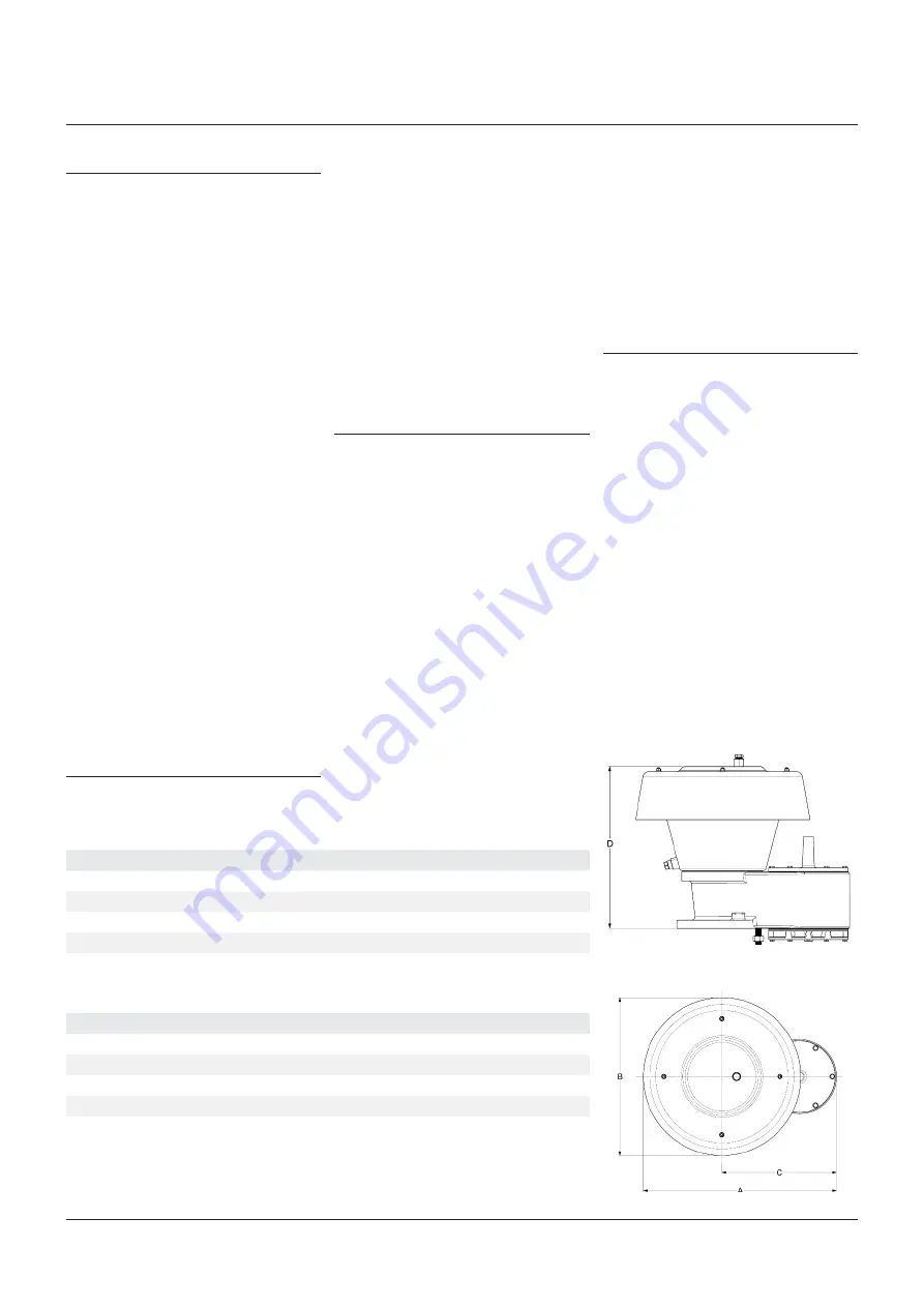
CONSTRUCTION
Refer to Figure 04 for construction and assembly
detail.
Standard materials of construction for the valve
include cast body and cover(s). Pallets are dead
weight loaded with lead or coated steel weights
and include a flexible membrane-sealing
insert. The pallet is loosely guided through a
center stem and pallet guide posts.
The maximum working pressure for the
5910C series unit is 2 psig (13.8 kpa). For
material selection see product data sheet.
Size
A [mm]
B [mm]
C [mm]
D
1
[mm]
2"
445
390
251
329
3"
505
390
311
360
4"
588
543
316
430
6"
666
543
395
503
8"
818
642
497
577
Size
A [in]
B [in]
C [in]
D
1
[in]
2"
17.52
15.35
9.88
12.95
3"
19.88
15.35
12.24
14.17
4"
23.15
21.38
12.44
16.93
6"
26.22
21.38
15.55
19.80
8"
32.20
25.28
19.57
22.72
1. Does not include coupling.
1. Does not include coupling.
Note: Minimum clearance for installation, to allow for appropriate air flow around the valve inlet
and outlet, should be 150 mm
protection measures, the overall safety of the
combined installation shall be assessed, taking
account of any hazardous area classification
(zones) and of the likelihood of possible ignition
sources.
WARNING
Ensure all selected materials are suitable for
the environment and processes for which they
are being installed. Attention must be paid
to selection of materials to ensure effective
operation of the valve and flame arrester
functionality.
variables must be evaluated to ensure safety.
The relative fire hazard of flammable mixtures
can be judged by the upper and lower explosive
limits. These limits are expressed as percent
by volume of the gas or vapor in air. The
explosive range is that span of concentrations
lying between the lower and upper limits. The
upper limit is the point at which the mixture
is too rich to burn, i.e., contains minimal
oxygen to support combustion. The broader
the explosive range, the easier it is to create
an air-gas explosive mixture. Conversely, when
an explosive range is narrow, the chance of
developing a hazardous air-gas mixture is
reduced.


