Safety
Information
Product
Information
Mechanical
Installation
Electrical
Installation
Getting
Started
Basic
parameters
Running
the motor
Optimization
SMARTCARD
operation
PC tools
Advanced
parameters
Technical
Data
Diagnostics
UL Listing
Information
108
Affinity User Guide
www.controltechniques.com Issue Number: 5
RFC
Pr
0.10
(
3.02
) indicates the value of motor speed that is obtained from
the speed estimator.
Pr
0.11
displays the frequency at the drive output.
Pr
0.12
displays the rms value of the output current of the drive in each
of the three phases. The phase currents consist of an active component
and a reactive component, which can form a resultant current vector as
shown in the following diagram.
The active current is the torque producing current and the reactive
current is the magnetizing or flux-producing current.
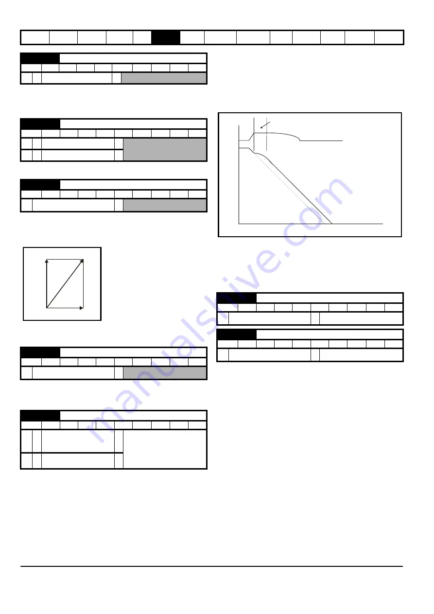
6.2.6 Ramp mode and Stop mode selectors
Pr
0.15
sets the ramp mode of the drive as shown below:
0: Fast ramp
Fast ramp is used where the deceleration follows the programmed
deceleration rate subject to current limits. This mode must be used if a
braking resistor is connected to the drive.
1: Standard ramp
Standard ramp is used. During deceleration, if the voltage rises to the
standard ramp level (Pr
2.08
) it causes a controller to operate, the output
of which changes the demanded load current in the motor. As the
controller regulates the link voltage, the motor deceleration increases as
the speed approaches zero speed. When the motor deceleration rate
reaches the programmed deceleration rate the controller ceases to
operate and the drive continues to decelerate at the programmed rate. If
the standard ramp voltage (Pr
2.08
) is set lower than the nominal DC bus
level the drive will not decelerate the motor, but it will coast to rest. The
output of the ramp controller (when active) is a current demand that is fed
to the frequency changing current controller (Open-loop modes) or the
torque producing current controller (RFC mode). The gain of these
controllers can be modified with Pr
4.13
and Pr
4.14
.
2: Standard ramp with motor voltage boost
This mode is the same as normal standard ramp mode except that the
motor voltage is boosted by 20%. This increases the losses in the motor,
dissipating some of the mechanical energy as heat giving faster
deceleration.
6.2.7 Sleep/wake mode
Sleep/wake mode automatically stops the motor if it is running at a low
and inefficient speed. It is enabled when Pr
0.15
is set to a non zero
value and activated when the absolute value of the frequency/speed
reference Pr
1.01
remains below the sleep threshold Pr
0.15
for the time
period set in Pr
0.16
.
When sleep/wake mode is activated, the internal drive run command is
removed and the motor stops. The motor restarts when Pr
1.01
remains
above the sleep threshold Pr
0.15
for the time period set in Pr
0.16
.
If the PID functions are being used then sleep mode can be delayed by
setting the PID pre-boost level (Pr
14.28
) and maximum boost time
(Pr
14.29
) to non-zero values.
Sleep/wake mode cannot be activated when the keypad reference mode
is selected (i.e. Pr
1.49
= 4).
If bipolar mode is disabled (i.e. Pr
1.10
= 0), then negative values of the
reference selected (Pr
1.01
) are treated as zero when compared to the
sleep threshold.
0.10 {3.02}
Motor speed
RO
Bi
FI
NC
PT
RFC
Ú
±Speed_max rpm
Ö
0.11 {5.01}
Drive output frequency
RO
Bi
FI
NC
PT
OL
Ú
±SPEED_FREQ_MAX Hz
Ö
RFC
Ú
±1250.0 Hz
Ö
0.12 {4.01}
Total motor current
RO
Uni
FI
NC
PT
Ú
0 to Drive_current_max A
Ö
0.13 {4.20}
Percentage load
RO
Uni
FI
NC
PT
Ú
±USER_CURRENT_MAX %
Ö
0.14 {2.04}
Ramp mode select
RW
Txt
US
OL
Ú
FASt (0)
Std (1)
Std.hV (2)
Ö
Std (1)
RFC
Ú
FASt (0)
Std (1)
Ö
Active
current
Total current
Magnetising current
0.15 {6.53}
Sleep/wake threshold
RW
Uni
US
Ú
±SPEED_FREQ_MAX Hz/rpm
Ö
0.0
0.16 {6.54}
Sleep/wake delay time
RW
Uni
US
Ú
0.0 to 250.0 s
Ö
10.0
DC Bus voltage
Motor Speed
Programmed
deceleration
rate
t
Controller
operational
Содержание Affinity
Страница 274: ...0474 0000 05 ...


