


Introduction and System Description
3
1.0
I
NTRODUCTION
AND
S
YSTEM
D
ESCRIPTION
Congratulations on your choice of the Liebert MP2-220N POD™ (3U POD). The 3U POD provides
maintenance bypass capability as well as power output distribution. The 3U POD can be used on
UPSs in the rack mount or tower configuration.
The 3U POD provides an isolated path of power for your UPS system for preventive maintenance or
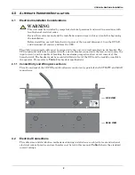
service. As shipped, cords and receptacles provide ready to use UTILITY and LOAD connections.
Optionally, the utility input and/or the load output may be converted to hardwiring,
1.1
System Description
The 3U POD has two modes of operation:
UPS
(UPS available) and
UTILITY
(maintenance bypass).
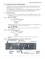
• In
UPS mode
, the power is routed through the UPS system delivering conditioned power to the
load, as shown in
Figure 1
.
Figure 1
UPS mode of operation
• In
UTILITY mode
, the power is routed around (bypassing) the UPS system (see
Figure 2
). Util-
ity power is supplied directly to the load through the 3U POD.
Figure 2
UTILITY/maintenance bypass mode
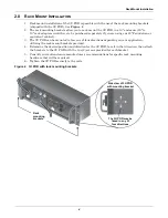
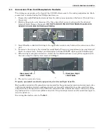
• In Utility mode, the UPS may be turned off and removed without affecting the load. See
Figure 3
.
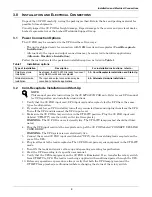
Figure 3
Front panel view showing plug-in connections to and from the UPS
!
CAUTION
Battery back-up and conditioned power are NOT available during the UTILITY mode
of operation.
Utility
POD
UPS
Connected
loads
Utility
Connected
loads
POD
UPS
UPS
AVAILABLE
UPS
UTILITY
OUTPUT
16A/208V~
OUTPUT
16A/208V~
OUTPUT
12A/208V~
ON
OFF
MAINTENANCE
BYPASS
AVAILABLE
CONNECT TO
UPS OUTPUT
IF UTILITY LAMP IS ILLUMINATED
MAINTENANCE BYPASS POSITION
MAY BE SELECTED
SWITCH TO UPS POSITION ONLY
WHEN UPS LAMP IS ILLUMINATED
16A/208V~
CONNECT UPS
LINE CORD HERE
CAUTION
LOAD
UTILITY
INPUT CORD FROM UTILITY
Connect to wall receptacle
Rotary switch and
power indicator lamps
Load connections
Connect
UPS input
cord here
CORD TO UPS
Connect to load receptacle of UPS
UTILITY PANEL
Remove for
hardwire
conversion
LOAD PANEL
Remove for
hardwire
conversion
Содержание 3U MP2-220N POD
Страница 1: ...POWER AVAILABILITY 3U MP2 220N POD USER MANUAL Power Output Distribution 208 Volt 16 Amp ...
Страница 2: ......
Страница 4: ...ii ...
Страница 16: ...Specifications 12 ...
Страница 17: ......


