background image

5-11

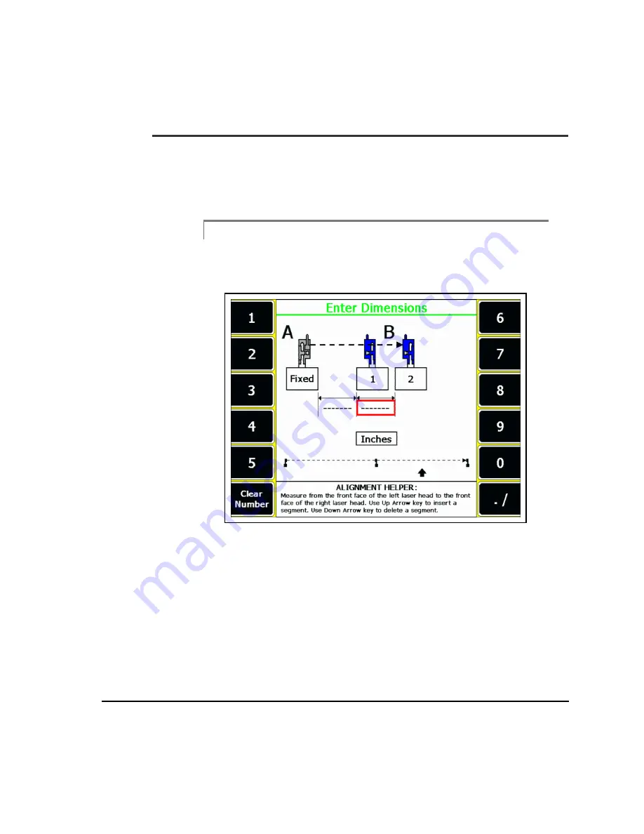
Straightness Enter Dimensions

The Enter Dimensions screen allows you to enter the dimensions for the profile 
being measured. The Enter Dimensions screen is reached by pressing the Enter 
Dimensions key on the Main screen.

Note

This section assumes that the fixtures are set up to the point that the 

laser heads are mounted.

Straightness Enter Dimensions Screen

Содержание 2130 RBM Consultant Pro

Страница 1: ...Reference Manual 2130 RBM Consultant Pro Laser Alignment Analyzer and Fixtures Part 97191 Rev 1 ...

Страница 2: ...ment Research Park Inerleuvenlaan 50 Leuven 3001 Belgium Phone 32 16 74 14 71 UK 441516779418 FAX 32 16 74 14 19 emacust emersonprocess com Asia Pacific Emerson Process Management Asia Pacific Pte Ltd 1 Pandan Crescent Singapore 128461 Phone 65 67708706 FAX 65 67708006 MHM TechSupport AP EmersonProcess com Worldwide Web http www MHM AssetWeb com AMS Machinery Manager Reference Manual This document...

Страница 3: ... any applicable maximum number of licensed users You may not relicense the Software or use the Software for third party training commercial time shar ing rental or service bureau use Client may not use the Software in as or with an ASP Application Service Pro vider Software Updates CSI agrees to provide you at no charge except for media preparation and shipping charges for one 1 year from the date...

Страница 4: ...t to other countries including without limitation the U S Export Administration Regulations U S Government Rights When provided to the U S government the computer software and related materials and documentation are provided subject to the same license rights as those enu merated above Hardware Technical Help 1 Please have the number of the current version of your firmware ready when you call The ...

Страница 5: ...ou go through Try to determine before you call whether the problem is repeatable 3 Please be at your computer when you call We can serve you better when we can work through the problem together Software Technical Support Emerson Process Management provides technical sup port through the following for those under support agreement Telephone assistance and communication via the Internet Mass updates...

Страница 6: ...vi ...

Страница 7: ...on 2 10 Battery Charging 2 11 Battery Usage Laser Heads 2 16 Precautions 2 17 Introduction to Laser Alignment Fixtures Setup 2 18 Attaching the Fixtures 2 19 Attaching the B821007 Carbon Steel Mounting Base 2 19 Attaching Chain to the Chain Pickup 2 20 Allowing Maximum Tightening Range 2 21 Positioning a Mounting Base 2 22 Positioning the Other Mounting Base 2 23 Attaching Excess Chain 2 24 Using ...

Страница 8: ...ic Alignment Steps 3 1 Advanced and Basic Laser Align Applications 3 2 Advanced Laser Align 3 2 Basic Laser Align 3 2 Main Screen 3 3 Three Step Alignment 3 5 Main Screen Function Keys 3 6 Alt Main Screen 3 7 Alt Main Screen Function Keys 3 8 Job Reset 3 11 Basic Mode 3 12 Basic Mode Function Keys 3 13 Job Reset 3 16 Machine Configuration Function Keys 3 18 Laser Align Alignment Method Function Ke...

Страница 9: ...he Foot Pre Check has been started 3 82 Acquiring Alignment Data 3 82 Auto Sweep 3 85 Manual Sweep 3 94 Accept Readings key 3 97 Auto 4 Point 3 100 Manual 4 Point 3 105 Dual Pass 3 111 Dual Pass Cable 8215C2 PM Models 821500 and 822500 Only 3 119 Review Results 3 121 Review Results Measurements Function Keys 3 124 Sweep Mode Curve Data 3 126 Data Quality 3 127 Move Machine 3 129 Vertical Move 3 13...

Страница 10: ... 4 3 Basic Vertical Alignment Steps 4 3 Three Step Alignment 4 5 Vertical Main Screen Function Keys 4 6 Vertical Alt Main Screen 4 7 Vertical Alt Main Screen Function Keys 4 8 Job Reset 4 10 Vertical Machine Configuration 4 11 Vertical Machine Configuration Function Keys 4 12 Laser Angle Advance 4 13 Laser Angle Advance Function Keys 4 14 Vertical Laser Configuration 4 15 Vertical Laser Configurat...

Страница 11: ...nter Dimensions 5 11 Straightness Move Laser Heads 5 15 Straightness Surface Profile 5 18 Chapter A Application Information Alignment Application Notes A 3 Pre job Preparation and Setup A 5 Changes That Occur During Operation A 6 Alignment Pitfalls A 8 Appendix B Foot Pre Check Types Foot Pre Check Measurement Methods Soft Foot and Frame Distortion Index FDI B 1 Appendix C Technical Specifications...

Страница 12: ...xii Batteries Analyzer Chargers D 2 Alignment Fixtures D 2 Customer Support D 3 Reliability Services D 4 Glossary Index ...

Страница 13: ...ightness measurements AppendixA providesgeneralapplicationoverviewinformationaboutpro cedures used in shaft alignment Note Thismanualcoversinformationspecifictothe2130RBMConsultant Pro Advanced Laser Alignment program It is assumed that the user is familiar with the general hardware and operation of the Model 2130 analyzer If any questions or concerns arise in using the analyzer refer to the 2130 ...

Страница 14: ...5 sometimes quoted as 8215 8225 refer to both the RF versions Models 821500 and 822500 and the direct connect only versions Models 821501 and 822501 laser systems except where information specific to one type of laser system is discussed ...

Страница 15: ...del2130analyzerprocessesthedataand calculates the required machine moves necessary to bring the machine compo nents into alignment Withmostalignmentsystemsavailabletoday thesagofthealignmentfixturesmust beconsideredtoaccuratelycalculatemachinemoves Withtheuseoflaserbeams there is no fixture sag to consider The RF communication between the sensor heads and the Model 2130 analyzer simplifies data ac...

Страница 16: ...nt measurement range Partial revolutions down to 45 Dual Pass method for uncoupled alignments Real time machine move monitoring vertical and horizontal Soft foot locator Radio frequency communication Direct cable connect if needed Automatic data acquisition Dual beam technology Internal angle sensors Internal memory 45 minute charge cycle for sensor heads Simultaneously charging sensor heads and a...

Страница 17: ... The caution paragraph alerts you to actions that may have a major impact such as lost data or damage to the analyzer or its accessories Warning Thewarningparagraphwarnsyouofactionsthatcouldcauseserious personal injury or death Analyzer Serialization The loaded firmware has been serialized and is matched to the analyzer serial number If the firmware and analyzerserial numbers do not match contact ...

Страница 18: ...BMCONSULTANT PRO firmware version v 6 3 8 0 or later The following 4 90 or later AMS Suite Machinery Health Manager files dated 08 08 2005 or later RBMcom exe RBMcomSr exe XFrAlg dll UltraAlg exe UltraMgr requires some planning and setup before jobs can be down loaded into thisalignmentprogram RefertotheappropriateUltraMgruser smanualformore information on communicating with the PC ...

Страница 19: ...re the contents of the package to your shipping invoice For additional assistance refer to the following fixtures case layouts If a discrepancy is found call Emerson Customer Support at 865 671 4274 Fixtures Case Layout bottom section Note Some parts shown in these illustrations may be optional in different packages ...

Страница 20: ...1 8 Fixtures Case Layout top section ...

Страница 21: ...tion Warning The8215 8225LaserAlignmentFixturesuseaClassII CDRH laser or Class 2 IEC laser This laser complies with 21 CFR 1040 10 and 1040 11safetyrequirementswithapoweroutput 1 0mW average and a pulse repetition of 600 pulses sec The pulse duration is 110 microseconds However donotexposethehumaneyedirectlytothe laser beam Warnings are located on each sensor head Warning Usingthecontrolsoradjustm...

Страница 22: ...2 2 Setting Up and Using Laser Alignment Fixtures Laser heads front view Laser heads rear view ...

Страница 23: ...2 3 Note Only the Models 821501 and 822501 direct connect only laser sys tems have CE approval Laser radiation caution ...

Страница 24: ...n the equipment is operated in a commer cial environment This equipment generates uses and can radiate radio frequency energy and if not installed and used in accordance withtheinstructionmanual maycauseharmfulinterferencetoradio communications Operationofthisequipmentinaresidentialareais likely to cause harmful interference in which case the user will be required to correct the interference at hi...

Страница 25: ...ent color front panels HeadAhasagrayfrontpanelwithwhitegridlinesandblueon offbuttons while head B has a blue front panel with white grid lines and gray on off buttons Note Throughout the manual photos may contain images of either the older or current versions of laser heads 1 RF Antenna RF Antenna Housing Direct Connect Port Targets PSD s Sensor Head ID Laser Source Charging Port Horizontal Laser ...

Страница 26: ... and the 8225 sensor heads arethetarget PositionSensingDetectororPSD size laserdistance andthefront overlay The 8215 sensor head has a 10mm x 10mm PSD and a laser which allows alignments over a sensor spacing up to30 feet or 9 meters The 8225 sensor head hasa20mmx20mmPSDandalaserwhichallowsalignmentsoverasensorspacing up to 100 feet 30 5 meters Although the direct connect only laser system Model 8...

Страница 27: ...s in the acceptable condition to perform an alignment No Action Required X flashing Sensor head in standby sleep mode When the Laser Head sees no activity for five minutes they automatically enter Sleep Mode to conserve battery power The color will be the one that was active solid or flashing before this state was entered When this sleep mode is entered the LED will be flashed off for 1 5 sec and ...

Страница 28: ...the LED will be flashed off for 0 5 sec and then flashed on for 0 5 sec Data is accepted when the battery is this state Recharge sensor heads X Major Error Refer to 6 Laser Head Status Screen on page 3 16 for more information on the error and the required action X flashing Low battery 2nd final warning sensor head The Laser Head has the ability to monitor its own battery power The battery power is...

Страница 29: ...SD the LED will be a solid yellow even when the beam is in the linear portion of the PSD Thebeamwillthenflash togreenwheneveravaliddatapointisacquired Thisdeviationisnecessarytoallow for the indication to the user that the Laser Heads are acquiring data as they are rotated past each other Note Todeterminetheactualerror selecttheCheckLasersoptiononthe Altscreen ThiswillactivatetheLaserHeadsStatussc...

Страница 30: ...Do not engrave on the sensor heads Keep all lens free of grease dirt oil and other smudges Clean the laser and target lens with a soft lint free cloth and standard lens cleaningsolution afieldsizecleanercontainerisavailablefromEmerson Never use an organic solvent such as a thinner or benzine Store sensor heads in protective hard shell carrying case when not in use Calibration The Model 8215 8225 c...

Страница 31: ...beidentifiedbyitssolidgrayfrontpanel The current version of the 8211 charger also uses a gray motif on the front panels but the area around the Fast and Discharge buttons is blue Model 8211 Smart Charger The Model 8211 charger provides all battery charging needs and comes with the system Itisa smart dropin chargerforthelaserheads itwillalsochargetheana lyzer when plugged into a cable The following...

Страница 32: ...into the 8211 charger in the top end cap At that time the beeper will sound indicating that power has been applied to the battery charger As a test all LEDs will illuminate for 1 5 seconds 4 Plug the analyzer charging cable into the bottom end cap Thesensorheadsandanalyzercannowbechargedeitherindividuallyor allatthe same time Charging the Sensor Heads with the Model 8211 Charger Drop them over the...

Страница 33: ...e voltage range Once the battery temperature and voltagearesuitableforcharging thechargerautomaticallybeginstricklecharging and the Trickle indicator light turns on To fast charge or discharge the battery the Fast button or Discharge button must be pressed If the Fast button or Discharge button is pressed while the battery voltageistoolowortemperatureisnotsuitableforFastorDischargeoperation the in...

Страница 34: ...arging and the Fast indicator light turns on If charging a former ver sion of the laser heads that contain NiCad batteries to avoid the battery memory concern usetheDischargemode when you havemore than 20 minutestocharge the sensor head batteries The typical charge cycle is as follows Note After power has been applied to the charger and the sensor head s placed in it if none of the LED s for that ...

Страница 35: ...ully discharged set of batteries is 45 minutes for the current version of the 8211 charger and 15 minutes for the former version of the 8211 charger The beeper will sound when both heads are fully charged and the charger switches to trickle Charging the Analyzer with the Model 8211 Charger Chargingfunctionsforthe8117 2120and2130analyzersareidenticalforboththe former and current versions of the 821...

Страница 36: ...mode thelaserbeamandRFcommunicationareshutdownuntilcom munication is reestablished All data in memory is saved In the auto shutdown mode the sensor heads are completely shutdown The Power Button starts the sensor heads again All data in memory is lost therefore another sweep should be taken The sleep and auto shutdown modes can be disabled To disable the sleep mode oneachlaserhead withthelaserhead...

Страница 37: ...swithanythingotherthantheproduct for which they are designed Do not use the 8211 charger to charge any thing else Donotuseanybatteriesotherthanthoseincludedand orspecifiedforthe analyzer and 8215 8225 laser heads DonotconnectaprinterdirectlytotheRS232portlocatedonthetoppanel of the analyzer DonotconnectanyadaptersoraccessoriestotheRS232portlocatedonthe top panel of the analyzer while the analyzer ...

Страница 38: ...ass 2 IEC laser This laser complies with 21 CFR 1040 10 and 1040 11safetyrequirementswithapoweroutput 1 0mW average and a pulse repetition of 600 pulses sec The pulse duration is 110 microseconds However donotexposethehumaneyedirectlytothe laser beam Warnings are located on each sensor head Watervaporordustcaninterferewithatarget seeing itslaser Theairbetweenthe sensorheadsshouldbevisuallyclear En...

Страница 39: ...erethelaserfixturescanberigidlymountedtoa shaft that can be rotated freely Select the chain tightener of choice The right photograph shows a knurled nut which can be tightenedbyhand Thehex nut mechanismprovides amore stable versatile mounting while the knurled nut is more convenient Use each nut as shown 2 These photographs illustrate how the chain assembly should be slipped into the mountingbase ...

Страница 40: ...Pickup This photograph illustrates how the chain attaches and actually clamps the shaft Thebaseisplacedontheshaft orcoupling andalinkofthechainisslippedinto thechainpickuptosecurethebasetotheshaft Afterslippingachainlinkintothe chain pickup tighten the bolt at the end of the chain ...

Страница 41: ...oallowformaximumtighteningrange ensurethatthechainnutisflushwiththe endofthechainbolt asshownbyarrow Noticethatthechainboltsareonoppo sitesides Asshowninlatersections eachmountingbasecanbeinstalledoneither end and the chain bolts placed on either side of the shaft ...

Страница 42: ...e of the mounting bases and rotateit along with the shaft until it is somewhatlevelatthetopoftherotation Totightenthemountingbase usea9 16inch wrench or your hand depending on which chain tightener is being used Caution Do not overtighten the chain the maximum tightening torque is 10 ft lbs ...

Страница 43: ... in relation to one another Althoughthispartoftheprocedureisnotabsolutelycritical placingthemounting bases relatively level with each other allows the laser beam adjustment to be more or less centered This ensures that the laser beams can line up with their targets easily Also there may be times when the top position is not accessible The objective of thisstepistomountthesensorheadsinthesamerotati...

Страница 44: ...either side to take up the slack As shown in the followingphotographs youcanuseeitherorbothoftheslotsasneeded Theorder of use is notimportant Infact the L slotcannot be usedwhen mountingto shafts or couplings greater than 3 inches 76 mm in diameter When fastening the chain into the T shaped slot the rubber block will hold the chain in place ThephotographbelowillustratesusingtheT shapedslot seethef...

Страница 45: ...2 25 Attaching the Fixtures Using the L shaped Slot Caution Do not attach excess chain prior to tightening the mounting base chain bolts Doing so may cause damage to the L and T shaped slots ...

Страница 46: ...lip You will almost always have a little extra chain left over In that case use the chain clip partnumberD22745 toattachittothepreviouschainloop Emersonrecom mends that you use this clip to help prevent the chain from sliding out of the L slot as the shafts are rotated ...

Страница 47: ...Installing a Post Screw a mounting post part number D23465 into each of the outer holes in the mounting base Tighten each post with the supplied tightener Phillips screw driver or with a 1 8 inch Allen wrench not supplied with kit ...

Страница 48: ...th letters on the front panel Place a sensor head on the two posts It does not matter on which side Head A or HeadBismounted theheadswillbeconfiguredintheanalyzer Adjusttodesired positionandtighteneachpostclampfingertight Themountingpostsallowupto 1 5 inches 38 mm of vertical adjustment If more vertical adjustment is needed use the vertical extension blocks See Introduction to Special Applications...

Страница 49: ...xtures Note Longer mounting posts are not available However if you wish to makeyourown refertothemechanicaldrawingofamountingpost in the section entitled Mounting Post part number D23465 For Alignment Brackets in Appendix B ...

Страница 50: ...antenna may have to be adjusted When the antenna is in its most uprightpositionitextendsupabovethetopofthelaserhead Holdingtheantenna housing not the antenna itself rotate or twist the antenna down or up dependingonitsstartingposition toitsdesiredposition Theantenna srotational arc is 30 degrees When the antenna is inthe down position it does not extend above the top of the laser head 3 ...

Страница 51: ...Models 821500 and 822500 RF Laser Systems Only Mounting the Other Sensor Head Install the opposite sensor head in the same manner Head A or Head B depending on which sensor head was mounted on the other side ...

Страница 52: ...r to achieve less than the typical operating range in an electrically noisy environ ment Note Thisequipmenthasbeentestedandfoundtocomplywiththelimits for a Class A digital device pursuant to Part 15 of the FCC Rules These limits are designed to provide a reasonable protection against harmful interference when the equipment is operated in a commer cial environment This equipment generates uses and ...

Страница 53: ...y can be transmitted When the sensor head is turned off the memory data is erased IftheanalyzerisoutofrangeofoneorbothsensorheadsorifsomesortofRFinter ference is occurring it will repeatedly attempt to communicate with the sensor heads Amessagewillbedisplayedontheanalyzeruntilthecommunicationlinkis established WhencommunicationusingRFbecomesdifficult Emersonrecommendsthatyou usetheDirectConnectlin...

Страница 54: ...0RF to 25 pin Connector Install the 8000RF Interface onto the serial port of the analyzer by completing the following steps 1 Ensure that the Model 2130 analyzer is turned off 2 Connectthe25 pinconnectorofthe8000RFInterfacetotheRS 232porton the Model 2130 analyzer 3 Turn the Model 2130 analyzer on ...

Страница 55: ...2 35 Models 821500 and 822500 RF Laser Systems Only Caution Donotrotateortwisttheantennaonthe8000RFInterface Attemptingtodoso will damage the unit The Attached 8000RF Interface ...

Страница 56: ...ents otherradiosystemsoperatinginthe vicinity at or near the same operation frequency and noise generated by nearby equipment all may make RF communication unsatisfactory Note BoththeA800001andA821510DirectConnectcableswillworkwith the8215 8225laserheadsforallmodesofoperationwherecommu nication between the laser heads and analyzer are necessary except for the Dual Pass mode Onlythe A821510cable ca...

Страница 57: ... not twist 4 ConnecttheLemoconnectorontheoppositeendofthecabletotheLemo port under the nose of each 8215 8225 Note When connecting the Lemo connector toits mating connector line up the red dots located on each connector with each other before completing the connections To complete the connection push the connectors together Do not twist 5 Turn the analyzer on Fromthispointon DirectConnectisveryeas...

Страница 58: ...ead and cable Pull the cable connector completely out of the sensor head connector before turning the cable The direct connect cable is 5 feet 1 5 m long with pigtail style cable When standing between the sensor heads a 6 feet 1 8 m span can be aligned depending on the diameter of the shaft Extension cables Model 800002 and Model 800003 are available for longer spans larger diameter shafts or if y...

Страница 59: ...on pigtail the total length is 13 feet 4 meters When standing between the sensor heads a 22 foot 6 7 meters span can be aligned depending on the diameter of the shaft 5 Note With the 8215 a maximum distanceof 30 feet 9 m between the laser heads can be achieved With the 8225 a maximum distance of 100 feet 30 5 m between laser heads can be achieved ...

Страница 60: ...tton options Warning Although the laser in the 8215 8225 system is low in intensity 1 0 mW never direct the beam at a human eye Use of controls or adjustments or performance of procedures other than those speci fiedbyEmersonmayresultinhazardouslaserradiationexposure To do so could result in serious personal injury Always ensure that the sensorheadsaremountedsecurelybeforeturningonthelaserbeam ...

Страница 61: ...Models 821500 and 822500 RF Laser Systems Only Center the Laser Beams CenterbothLasersontheirassociatedtargetbyadjustingthethumbwheelsonthe front of each sensor head Vertical Adjustment Horizontal Adjustment ...

Страница 62: ...abilitiesofthe analyzer Visible Beam Rough Alignment This adjustment must be performed in each of the movement planes typically horizontal and vertical when required A horizontal adjustment is illustrated in the following figure duplicate the actions for vertical adjustments Rough Horizontal Laser Beam Adjustments 1 Center laser beams in respective targets 3 Estimate distance moved by laser beam L...

Страница 63: ...houldassistyouindeterminingtheapproximate movement s neededtoroughthemachinesin Gridlinespacingis0 3inches 7 5 mm Thefollowingtableshowsrecommendedmovesbaseduponthegrossmove ment of the laser beam on the sensor head Gross movements are discussed in ver tical terms for simplicity 6 ...

Страница 64: ...ected Formoreinfor mation about sweep data collection modes see Chapter 6 Gross Movement Recommended Machine Move at Gearbox at Motor Small Large down Angular Offset add shims under the inboard Gearbox feet or remove shims from the outboard Gearbox feet Large down Small Angular Offset add shims under the inboard Motor feet or remove shims from the outboard Motor feet Large up Large down Offset add...

Страница 65: ...s Only This procedure also works when using the Dual Pass mode Note Roughinginthemachinesothatthelaserbeamiskeptonthetarget PSD as the laser fixtures are rotated can be quicker with a larger PSD e g with the 20x20mm PSD on the 8225 laser fixtures ...

Страница 66: ...iame ters shafts 8 inches 203 mm and using alternative mounting brackets Nor mally additional blocks are used to achieve greater coupling clearance In some cases youmayfindthatone orboth ofthemountingblocksmustbeinstalledon the coupling itself For larger diameter shafts or mounting on a coupling addi tional lengths of chain may also be needed to mount the base ...

Страница 67: ...ater coupling clearances when using the B821007 carbon steel mounting bracket and the A800052 soft mount non rotational mounting bracket Mounting a One inch 25 mm Block This photograph shows a 1 inch 25 mm block being mounted onto the mounting block itself Note Emerson recommends that you tighten all vertical mounting block cap screws to 50 in lbs without lubrication ...

Страница 68: ...2 48 Setting Up and Using Laser Alignment Fixtures Adding a 2 inch 51 mm Block Thisisapictureofa2 inch 51mm blockbeingattachedontopofthe1 inch 25 mm block the blocks can be stacked in either order ...

Страница 69: ...g Blocks 7 Thisshowsthecomplete3 inch 76mm extensionsetup Thefollowingtablelists which blocks are to be used for the various vertical extension ranges For Vertical Extension Length inches Use These Block s inches 0 0 1 1 2 2 3 1 2 ...

Страница 70: ...sible Occasionally you may have to mount the bracket on a coupling This view shows the B821007 carbon steel mounting brackets being mounted to the shaft on one side and the coupling on the other In order to do this you may havetouseaverticalextensionblock s Intheexampleshownabove a1 inch 25 mm extension block is being used on the right side no block is used on the left coupling side ...

Страница 71: ... bracket part number D22773 and the A800052 soft mount non rotational mounting bracket part numberA832001 Inadditiontothechainitself extensionkitsincludeaclevispin and a hair pin which are used to connect the sections of chain together Refer to the following table to determine chains needed with various shaft diame ters ForShaftDiametersInches mm Use These Chain Lengths Less than 8 203 Standard Ch...

Страница 72: ...oxes and hammer mills This bracket is typically used for uncoupled align mentswhereeithertheManualSweeporDualPassmethodsarebeingused Ithas eightshieldedballbearingsmountedatthebaseofthebracketsothatthebracket actually rolls around the shaft Nylonnutsthatcomeinthepackagecanbeaddedtothechaintoallowittoeasily slide over the shaft while providing a stable mounting configuration If necessary installthe...

Страница 73: ...seontheshaft orcoupling alinkofchainisslippedintotheT slotto securethebasetotheshaft Thesoft mountbasedoesnothaveachainpickuplike the B821007 Carbon Steel Mounting Base After slipping a chain link into the T slot tighten the bolt at the end of the chain Each mounting base can be installed on either end and the chain bolts placed on either side of the shaft Take up any slackinthechainusingthechainc...

Страница 74: ...ixtures Caution Toensuremeasurementaccuracy thecontactsurfacesoftheshaft orcoupling must be free of dirt grease oil etc If cleaning is needed Emerson recommends thatyouuseasolvent basecleaner Shaftkeysshouldbeavoidedtoreduceerrors in accuracy 9 ...

Страница 75: ... 1 2 inch 13mm cou pling nut for especially tight spaces The bolts are hinged and can swing freely A cotter pin can be inserted into the bracket to prevent the bolt from swinging 10 Place the top v shaped bar section base of the bracket on the shaft and the bottomv shapedbarsectionofthebracketontheshaft ontheoppositesideofthe shaft from where the top v shaped bar section has been placed to secure ...

Страница 76: ...en with the suppliedtightener Phillipsscrewdriver orwitha 1 8inchAllenwrench not supplied with kit Mount the laser fixtures to the posts as described in Attaching the B821007 Carbon Steel Mounting Base on page 2 19 The photograph shows the base mounted to a shaft 11 Note Extension blocks are not available for this bracket ...

Страница 77: ...seandslipthecylinderintoits cradle To ensure maximum tightening range each nut should be flush with the end of the tightening bolt 12 Placethebaseontheshaft orcoupling andalinkofchainisslippedontothepin locatedontheoppositesideofthebrackettosecurethebasetotheshaft Afterslip pingachainlinkontothepin tightentheboltattheendofthechain Thebracket isheldinplacebya1 2inch 13mm couplingnutforespeciallytig...

Страница 78: ...crewdriver orwitha 1 8inchAllenwrench not supplied with kit Mount the laser fixtures to the posts as described in Attaching the B821007 Carbon Steel Mounting Base on page 2 19 Once the posts are in place mount the laser fixtures to the posts The photograph shows the base mounted to a shaft 13 Note Extension chains and blocks are not available for this bracket ...

Страница 79: ...c material Recommended minimum coupling diameter is 3 4 inches 75 100 mm where the shaft can be rotated freely Each bracket consists of a light weight delron housing containing seven powerfulrare earthmagnets Thebracketlipoverhangsthecouplingrimto provide extra stability With this accessory it is possible to attach the alignment fix tureswithinsecondsoftaggingoutamachineforso called hotalignment c...

Страница 80: ... 8inchAllenwrench not supplied with kit Mount the laser fixtures to the posts as described in Attaching the B821007 Carbon Steel Mounting Base on page 2 19 Attach the base to the insideoroutsideofthecoupling dependingonthecouplingdesignandwhether or not you are performing a coupled or uncoupled alignment The photograph illustrates the base attached to the outside of a coupling 15 ...

Страница 81: ...r thefunctionalityof any soft key is available This is accessedby pressing the 2130 analyzer Help key once andthenpressingthesoftkeyforwhichhelpisdesired PressingtheHelpkey twice returns a help message for the active program screen If further help is required refer to the appropriate section s in this manual Basic Alignment Steps Three basic steps are required to complete an alignment job 1 Define...

Страница 82: ...gnsoftkey Whentheadvancedapplicationisselected youwillhaveaccesstothe full functionality described throughout this manual The ability to perform basic laser align jobs is included in this program Basic Laser Align If the Basic Laser Align application is loaded in a 2130 analyzer the program can be launched by pressing the Basic Laser Align soft key on the 2130 analyzer home page When the basic app...

Страница 83: ...llustrated below Laser Align Application Main screen at job start Theapplicationdefaultstoapredefinedsetupwhenanewjobiscreated Thetype ofjob JobID EquipmentID alignmentmethod numberofmachinemoves and numberofnotesattachedtothejobaredisplayedintheupperportionofthemain screen Note Unless otherwise noted any defaults listed are displayed only at first Onceafieldismodifiedfromthedefault theprogramuses...

Страница 84: ...startedthenextuncompletedstepinthe recommended procedure is highlighted An X signifies a completed step Asyoucomplete steps thenext recommended step is highlighted Initially the Move Machine step is displayed but grayed out until you ve completed first two required steps which are critical to the alignment jobs Up and Down Arrow keys UsetheUpandDownArrowkeystohighlighteachfeature Ifyouselectaninac...

Страница 85: ...three steps 1 enter dimensions enter machine dimensions ifthermalgrowthisenabled enterthermalgrowthinformation otherwise this step is skipped 2 sweep laser heads iffootpre checkisenabled performSoftFootorFDIcheck otherwise this step is skipped acquire alignment data to determine the alignment condition of the machine 3 move machine review vertical moves review horizontal moves perform a live move ...

Страница 86: ...abled a Soft Foot or FDIcheck can also be performed from under this step Refer to the Sweep Laser Heads section on page 3 75 for more informa tion Move Machine Use the Move Machine key to advance to the Vertical Move screen where the machinemovesandalignmentconditionfortheverticaldirectioncanbereviewed This is the third step of the three key operation used in performing an alignment job AftertheVe...

Страница 87: ...The Alt Main screen also known as the Main Menu Alt2 screen allows you to setup alignment job parameters and job flow The Alt Main screen is reached by pressing the Alt key on the Main screen Laser Align Application Alt Main Advanced Mode ...

Страница 88: ...ning message will be displayed asking you if this is trulytheoperationtobeperformed Ifyouansweryes thenanydatastoredonthe joboranysettingsotherthanthedefaultswillbeclearedandyouwillremainatthe Alt Main screen If you answer no then the operation is aborted and you will remain at the Alt Main screen Machine Config Use the Machine Config key to advance to the Machine Configuration screen where the ma...

Страница 89: ...page 3 34 for more information Job Flow Use the Job Flow key to define certain job flow parameters for the job These parametersconsistofenteringthermalgrowthinformation performingafootpre check defining live move options enabling a live move audible tone and flashing LED option and reviewing and averaging multiple acquisitions together Refer to the Job Flow section on page 3 42 for more informatio...

Страница 90: ...3 10 Horizontal Alignment ...

Страница 91: ...efault parameters Before any defaultsareloaded awarningmessage willbedisplayedaskingtheoperatorifthis is truly the operation to be performed If the operator answers yes then the job defaults are loaded and all job data is cleared and the operator remains at the Alt Main screen If the operator answers no then the operation is aborted and the operator remains at the Alt Main screen Load Default Tole...

Страница 92: ...ctionality describedthroughoutthismanualwillbelimitedtothesubsetdescribedinthissec tion Laser Align Application Alt Main Basic Mode Except for differences in the alignment job parameters available under the Alt Main screen the procedure for performing a basic alignment is exactly as it is for anadvancedalignment TheAltMainscreenisreachedbypressingtheAltkeyon the Main screen ...

Страница 93: ...fore the option to do so is not available All basic horizontal jobs use Mach A as the left machine component and Mach B as the right machine component Laser Align Method UsetheLaserAlignMethodkeytotogglethealignmentmethodbetweentheonly two options available in Basic mode Auto Sweep default and Manual 4 Point RefertotheAcquiringAlignmentDatasection onpage3 82formoreinformation about these two metho...

Страница 94: ...ic mode The Laser Head A and B locations can not be changed therefore the option to do so is not available For all basic horizontal jobs Laser Head A must be located on the left machine and Laser Head B must be located on the right machine Job Manager Use the job Manager key to advance to the Job Manager screens where a new job canbecreatedfromscratchusingdefaultjobsetups anewjobcanbecreatedusing ...

Страница 95: ...d and averaged together Thermal Growth Use the Thermal Growth key to define whether or not thermal growth informa tion at the feet is to be entered for the job When selected the selection is toggled between being enabled and disabled default When this option is enabled you are able to input the amount of vertical and horizontal thermal growth at each machine foot Refer to the Entering Thermal Grow...

Страница 96: ...e job defaults are loaded and all job data is cleared and the operator remains at the Alt Main screen If the operator answers no then the operation is aborted and the operator remains at the Alt Main screen Load Default Tolerances Use the Load Default Tolerances function to load default alignment tolerances Before any defaults are loaded a warning message will be displayed asking the operator if t...

Страница 97: ...achine Config key on the Alt Main screen Machine Configuration Screen Whenthisoptionisfirstselected themachinetypedefinedfortheleftmachinewill be highlighted by a red box around the machine type by default The default machine types for the left and right machines are Mach A and Mach B Up Down Left and Right Arrow keys Use Up Down Left and Right Arrow keys to select between each of the machine type...

Страница 98: ...ne types can be defined for the job Machine Types Machine Configuration Function Keys Select Left Machine UsetheSelectLeftMachinekeytosettheleftmachinecomponenttothemachine type highlighted by the red box Select Right Machine Use the Select Right Machine key to set the right machine component to the machine type highlighted by the red box ...

Страница 99: ...hod From the Laser Align Alignment Method subwindow you can select the align ment method for the current job The Laser Align Alignment Method sub window is reached bypressing theLaserAlign Method key onthe AltMainscreen Alignment Method Subwindow ...

Страница 100: ...gofdatain ordertoreducethenoiseinthedatabyaveragingalloftheacquiredvalues Inthis modeofoperation oncethedirectionofrotationisdefinedbythelaserheads any previous data stored is averaged with any new data acquired at the same angular position if the laser head has been moved at least 20 in the reverse direction or a full 360 sweep is performed Target Window UsetheTargetWindowkey ifthealignmentmethod...

Страница 101: ...e PSD s vertical center lineinwhichdatawillbeacquiredasthelaserbeampassesacrossthe window Sample Rate Use the Sample Rate key if the alignment method is Manual Auto 4 Point or Manual4Point tosetthenumberofsamples intherange1to25 tobeaveraged togethertogenerateasinglereading Twosamples default aretypicallysufficient but for example if too much background vibration is present you may want to increas...

Страница 102: ...key on the Alt Main screen Tolerance Type Subwindow Tolerance Type Function Keys Tolerance Type UsetheToleranceTypekeytodefinethetolerancetypeforthejob Whenselected the selection is toggled between Standard default and Jackshaft Standardtolerancesarethecombinationofoffsetandangle Thistolerancetypeis a direct indication of the alignment condition Optimum alignment occurs when offset and angle are z...

Страница 103: ...o define whether the F dimension is to be estimated When selected it is toggled between being enabled and disabled default When enabled the program will estimate the F dimension to be one half of the C dimension If the Tolerance Type is Jack shaft the F dimension is not required Laser Configuration From the Laser Configuration screen you can configure the location for each of the laser heads durin...

Страница 104: ...anel and in addition can be distinguished by the color of the front panels Head A has a gray front panel with white grid lines while Head B has a blue front panel also with white grid lines Note AroutineintheprogramisusedtosensewhethertheModel8215or the Model 8225 laser heads are being used Laser Configuration Function Keys Change Laser Config Use the Change Laser Config key to toggle configuratio...

Страница 105: ...ssontheAltLaserCon figurationscreen Thisoptionisusefulifforsomereasonthedatatransferfromthe headstotheanalyzerwasabortedbeforecompletion Onceretrievaliscomplete a check of the data will be made Once this is complete you will be advanced to the main screen where the Move Machine program step will be highlighted Note Datastoredinthelaserheadsclearswhentheyareturnedofforwhen initialized ...

Страница 106: ...sing the Laser Address Selection key on the Laser Configuration screen Current Addresses Screen From this screen only the addresses setup in the analyzer and not the addresses setupinthelaserheadsthemselvesaredisplayed Toreviewtheactualaddresssetup in Head A with Head A turned on and Head B turned off select Read Head A Address ToreviewtheactualaddresssetupinHeadB withHeadBturnedonand Head A turne...

Страница 107: ...fferent address than the other For example one laser system can have the address of its Head A set to 1 Head B to2 andanalyzerto11whiletheotherlasersystemcanhavetheaddressofitsHead A set to 3 Head B to 4 and analyzer to 12 A maximum of 5 laser systems commu nicating RF can be configured to operate using different addresses Thedefinitionof operatingincloseproximity willvaryfromoneenvironmentto anot...

Страница 108: ...d Address Subwindow When the Received Address subwindow is displayed the actual address setup in Head A also displays If the address is not correct or you wish to change it type in the new address from 1 default to 10 then press the Enter key to accept the change and return to the Current Addresses screen The new address must be dif ferent than the Head B address If the address is correct press En...

Страница 109: ...dure for Head B is the same as described above for Head A except in this case Head B is turned on and Head A is turnedoff If a new address is entered it must be different than the Head A address Set Analyzer Address key Use the Set Analyzer Address key to read and set the address in the analyzer The analyzer address can be set from 11 default to 15 Note If you enter a number outside the range of 1...

Страница 110: ...Laser Head Status screen you can check the operational status of the heads and change the sample rate The Laser Head Status screen is reached by pressing the Check Lasers key on the Laser Configuration screen Laser Head Status Screen show bar graphs ...

Страница 111: ...3 31 Laser Address Selection Laser Head Status Screen show numbers Note Both laser heads need to be turned on for this option to function properly ...

Страница 112: ...t if too much background vibration is present for example you may want to increase the number of samples to 25 This option can also be changed from the Alignment Method subwindow When acquiring alignment data under the Sweep Laser Heads step if the align ment method is Auto Sweep or Dual Pass the sample rate can not be changed Decrease Sample Rate UsetheIncreaseSampleRatekeysimilarlyasyouwouldtheI...

Страница 113: ...3 33 Laser Address Selection Show Laser Angle Use the Show Laser Angle key similarly as you would the Hide Laser Angle key except this key is used to show the laser angle if it is hidden ...

Страница 114: ...he analyzer The Job ManagerscreenisreachedbypressingtheJobManagerkeyontheAltMainscreen Job Manager Screen TheJobIDandEquipmentDescriptiondefinedforthehighlightedjobdisplayson theuppersectionofthescreen Theactivelocationdisplaysjustbelowthejobinfor mation Thelistofjobsstoredontheactivelocationdisplaysonthelowersectionof the screen Whenthisscreendisplays theactivejobishighlighted Ifnojobsarestoredon...

Страница 115: ...tJobSetupsection onpage3 38 for more information Select Unselect UsetheSelect Unselectkeytochoosethehighlightedjob placeacheckmarkjust to the left of the job name If the job has already been selected clear the check mark to remove the job This operation does not delete the job Select Unselect All UsetheSelect UnselectAllkeytoselectalljobs placeacheckmarkjusttotheleft ofall job names and removeall ...

Страница 116: ...r Refer to the Transferring Alignment Job Data and Tolerances section on page 3 184 for more information In theBasic Laser Alignprogram jobs can not betransferred to and from thePC therefore this option is not available Copy Job Use the Copy Job key to create a copy ofthe highlighted job Before the job is copied youaregiventhechoiceofcopyingthejobwithallacquireddataorwithout the acquired data The ...

Страница 117: ...he highlighted job will toggle from top to bottom and vise versa with these keys The keys are only active when more than one job is listed Page Up and Down Arrows Use the Page Up and Down Arrow keys to scroll through the list of jobs one page at a time These keys are only active when more than one page of jobs is listed ...

Страница 118: ...e Edit This Job soft key to advance to the Edit Job Setup screen where the jobparametersusedforjobidentificationandstoragemaybeedited TheEditJob Setup screen is reached by pressing the Edit This Job key on the Job Manager screen Edit Job Setup Screen ...

Страница 119: ...thejobtransfercompletes thejobshouldbe assigned to its machine The Equip ID Equip Desc and Area will be modified to match their assignment within UltraMgr Ifnomachineorstationexists intheUltraMgrdatabase theycanbecreatedafter the job has been transferred You can then complete the job assignment Note If the job is defined within UltraMgr the Equip ID Equip Descrip tion Area and Coupling cannot be m...

Страница 120: ...key to edit the Coupling Number This option is usefulifthemachinerybeingalignedhasmorethanonecoupling Eachcoupling shouldhaveauniquenumber Anexamplewouldbeamachinerytrainconsisting of a motor a gearbox and a compressor The coupling between the motor and gearbox should be 1 and the coupling between the gearbox and compressor should be 2 The Coupling Number must be in the range 1 default to 10 Set M...

Страница 121: ...rtheinforma tion setup under Edit Job Setup loads into the job If you answer no then the operation is aborted In the Basic Laser Align Program only horizontal alignment jobs can be created therefore this option is not available Edit User ID Use the Edit User ID key toedit the User ID This optionis useful for identifying who performed the alignment Normally it will be the user s initials The User I...

Страница 122: ...w for the current job These optional parameters include enteringthermalgrowthinputs performingafootpre check performing averticallivemove enablinganaudibletoneandflashingLEDduringalivemove and review alignment results and data averaging The Job Flow subwindow displays by pressing the Job Flow key on the Alt Main screen Job Flow Subwindow ...

Страница 123: ...r a live move can be accomplished in the vertical direction When selected Live Move toggles between Horizontal Only default and Vertical and Horizontal When Horizontal Only is selected the Live Move option is not active on the Vertical Move screen On the Dual Move screen thelivemovecanonlybeperformedinthehorizontaldirection RefertotheMove Machine section on page 3 129 for more information Enable A...

Страница 124: ...dibletonewillnotbegeneratedasdescribedabove Inthis case only the analyzer LED will flash as described above When the Enable Alert option is disabled the analyzer LED will not flash and an audibletonewillnotbegeneratedwhenthemachinealignmentconditionreaches the target tolerance values Review Results UsetheReviewResultskeytoenableordisable default theReviewResultsoption in the Job Flow When enabled ...

Страница 125: ...ermal growth is enabled thermal growth information can also be entered from under this step The Enter Dimensions screen is reached by pressing the Enter Dimensions key on the Main screen Note This section assumes that the fixtures are set up to the point that the laser heads are mounted Enter Dimensions Screen both machines moveable ...

Страница 126: ...nomachinemoves for that machine can be given ThemachineRPMshouldbeuniqueforeachcouplingthatisdefinedforthisjob Ifyouhaveavariablespeedmachine enterthehighestRPMatwhichthecoupling operates Also ifacouplingdesignhasshaftsoperatingatdifferentspeedsenterthe larger of the two This parameter is used to establish alignment tolerances Although you are not required to enter the RPM before acquiring data it...

Страница 127: ... thenyouwilladvancetothenextstepintheprocedure Also ifthe CdimensionismissingandtheFootPre Checkoptionhasbeenenabled itwillbe disabledbeforeadvancing Ifyouanswerno thentheoperationisabortedandyou remain at the Enter Dimensions screen IfonlytheRPMand CandFdimensionshavebeenentered thentheQuickSpec mode will be activated In Quick Spec mode only the Angle Offset data will be available nomachinemovesw...

Страница 128: ...en the operation is aborted and you will remain at the Enter Dimensions screen IftheBdimensionistheonlyinputmissing thennoalternatesolutionswillbeavail able for the left machine If the D dimension is the only input missing then no alternatesolutionswillbeavailablefortherightmachine Ineithercase awarning message will be displayed before continuing The warning message informs you that the missing di...

Страница 129: ...e the laser face place a negative sign in front of it 1 8 inch 3 mm C Measure from the inside face of one laser head to the inside face of the other laser head 1 16 inch 1 5 mm D Center of inboard foot on the right machine to the laser head on the right machine To enter a measurement for a foot that falls inside the laser face place a negative sign in front of it 1 8 inch 3 mm E Center of outboard...

Страница 130: ...etheEnterkeytoadvance to eithertheSweepLaserHeadsstep orthe thermal growth screen s If the Thermal Growth option is not enabled once all required dimensions have been entered the Enter Dimensions step back on the Main screenwillbemarkedcompletedandtheunitadvancestotheSweepLaserHeads step IftheThermalGrowthoptionisenabled thedisplayadvancestothethermal growth screen s ...

Страница 131: ...sh thedecimal andforwardslash charac terscanbeusedtoenterfractionalvaluesonnumericentryscreensinwhichthese two characters are available The decimal character is used to separate the integer part from the fractional part of the numerical value Entering a fractional value of 5 3 4 ...

Страница 132: ...isentered showninthescreenabove it will beconverted to5 75 shownin the screen below when either another dimen sion is selected or the Enter key is pressed to accept the screen and advance to the next step in the procedure Factional value of converted to 5 75 5 3 4 ...

Страница 133: ...M and C and F dimensions if any of the fol lowingdimensionsaremissing theQuickSpecmodewillbeactivated Refertothe Enter Dimensions section on page 3 45 for more information InthisMode onlytoleranceplotinformationwillbeavailablesincemachinemove information can not be calculated without machine dimensions For this reason the tolerance plot screens will be displayed immediately after data has been acq...

Страница 134: ...he Main screen without checking the Move Machine program step on the Main screen as com plete If Retake Data is selected data is cleared and you advance to the first screen of the Sweep Laser Heads step In the Quick Spec mode no more than one set of data can be stored on the job IfAlignStandardMachineisselected dataremainsstoredandyouadvancetothe Enter Dimensions screen where the machine dimension...

Страница 135: ...faceSolutionscreenwherethealign mentconditionandmachinemovescanbeviewed RefertotheC faceAlignment section on page 3 175 for more information Note To perform a C face alignment the tolerance type can only be Stan dard If the job has a tolerance type of Jackshaft defined when you selecttheAlignC faceMachineoptionamessagewillbedisplayed If you answer yes then the tolerance type will be changed to Sta...

Страница 136: ... informa tion about thermal growth Note The larger PSD on the Model 8225 is capable of handling larger amountsofthermalgrowththanthesmallerPSDontheModel8215 TheLaserAlignprogramallowsyoutoinputtheamountofthermalgrowthatthe machinefeet oratthemachineprofilepositions whicharethenconvertedtothe corresponding movement at the machine feet It also consists of the following threemethodsofconvertingfromta...

Страница 137: ... the screen Theamountofverticalthermalgrowththatbothmachineswillexperienceduring operationcanbeexpressedineithermilsormillimeters mm dependingonthe analyzerunits Thermalgrowthvaluesshouldcorrespondtotheamounteachshaft movesin thevertical and horizontal directionsdirectlyaboveeachfoot Ifthermal growthisnegligible eitherleaveitblankorenterzeroes Atleastonenon zerovalue mustbeenteredbeforecontinuing ...

Страница 138: ...uld be used for the horizontal direction Up Down Left and Right Arrow keys UsetheUp Down Left andRightArrowkeystoselectthefieldyouwanttomodify highlighted with the red box around it Enter key Use the Enter key to advance to either the Foot Pre Check screens or the data acquisition screens Once all required dimensions have been entered the Enter Dimensions step back on the Main screen will be marke...

Страница 139: ...u to enter the dimensions for the profilelocationsandtheirrelationshipwithrespecttothemachinefeetlocationsas defined in the Enter Dimensions screen Profile P1 far right of the screen is located withrespect tothemachine configuration as defined for thejob The loca tion of each profile is displayed as a reference only Dimensionscanbeexpressedineitherinchesormillimeters mm dependingon the analyzer un...

Страница 140: ...tion about entering fractions Refer to the following table for a description of each dimension Left and Right Arrow keys Use the Left and Right Arrow keys to select the field you want to modify high lighted with the red box around it Dimension Measurement Description Measure to the Nearest I Profile P4 to the center of outboard foot of the machine on the left 1 8 inch 3 mm J Profile P4 to profile ...

Страница 141: ...en The amount of thermal growth that both machines experience during operation can be expressed in either mils or millimeters mm depending on the analyzer units Thermal growth values should correspond to the amount each shaft moves in theverticalandhorizontaldirectionsateachprofilelocation If thermalgrowth is negligible leave it blank or enter zeroes At least one non zero value must be enteredbefo...

Страница 142: ...n If one or both machines experience a growth to the right during operation then negative numbers should be used for the horizontal direction Up Down Left and Right Arrow keys UsetheUp Down Left andRightArrowkeystoselectthefieldyouwanttomodify highlighted with the red box around it Enter key Use the Enter key to advance to the Growth at Feet screen Growth at Feet ...

Страница 143: ...h shaft moves in the vertical and horizontal directions directly above each foot Note If one or both machines actually experience a downward growth during operation then negative numbers are used for the vertical direction If one or both machines experience a growth to the right duringoperation thennegativenumbersareusedforthehorizontal direction Edit Growth Values key Use the Edit Growth Values k...

Страница 144: ...h machine foot This method consists of the following three screens Enter Gap Offset Dimensions The Enter Gap Offset Dimensions screen allows you to enter the dimensions for the coupling and its relationship with respect to the machine feet locations as defined in the Enter Dimensions screen Dimensionscanbeexpressedineitherinchesormillimeters mm dependingon the analyzer units All dimensions must be...

Страница 145: ...tion of each dimension Left and Right Arrow keys Use the Left and Right Arrow keys to select the field you want to modify high lighted with the red box around it Dimension Measurement Description Measure to the Nearest U Diameter of the coupling This is also the circumference of the coupling divided by 3 14 pi 1 8 inch 3 mm V Center of inboard foot on the left machine to the sensor location on the...

Страница 146: ...unt of thermal growth that both machines will experience during opera tion can be expressed in either mils or millimeters mm depending on the ana lyzer units If thermal growth is negligible either leave it blank or enter zeroes At least one non zero value must be entered before continuing The range of values thatcanbeenteredforboththegapandoffsetare0to2048milsor0to52 02mm Gapisthedifferenceintheco...

Страница 147: ...nding direction Set Direction keys UsetheSetDirectionkeystodefinewhetherthecouplinggapisopenatthetopor bottomandtosetwhetherthecouplingoffsetoftheleftmachineishigherthanthe right machine or the coupling offset of the right machine is higher than the left machine for the corresponding direction Enter key Use the Enter key to advance to the Growth at Feet screen The Growth at Feet screen displays th...

Страница 148: ...t each machine foot This method consists of the following three screens Enter Face Rim Dimensions The Enter Face Rim Dimensions screen allows you to enter the dimensions for the coupling and its relationship with respect to the machine feet locations as defined in the Enter Dimensions screen Dimensionscanbeexpressedineitherinchesormillimeters mm dependingon the analyzer units All dimensions must b...

Страница 149: ...eft and Right Arrow keys Use the Left and Right Arrow keys to select the field you want to modify high lighted with the red box around it Enter Face Rim Dimensions measurement location Dimension Measurement Description Measure to the Nearest U Diameter of the coupling This is also the circumference of the coupling divided by 3 14 pi 1 8 inch 3 mm V Center of inboard foot on the left machine to the...

Страница 150: ... Total Indicator Runout For example if the left machinewastobeset3milshigh thenifthesensorlocationwasspecifiedtobeon theleftmachineshaftandthetoptargetreadingwas0 0 thebottomreadingwould be 6 0 mils With the same conditions and the sensor specified to be on the right machine shaft the bottom reading would be 6 0 mils Enter key Use the Enter key to advance to the Enter Face Rim Target screen Enter ...

Страница 151: ...e face and rim readings are 2048 to 2048 mils or 52 02 to 52 02 mm Left and Right Arrow keys Use the Left and Right Arrow keys to select the field you want to modify high lighted with the red box around it Enter key Use the Enter key to advance to the Growth at Feet screen The Growth at Feet screen displays the calculated vertical and horizontal thermal growth at each machine foot Refer to the Gro...

Страница 152: ...ng three screens Enter Reverse Dial Dimensions TheEnterReverseDialDimensionsscreen allowsyoutoenterthedimensionsfor the sensor locations and their relationship with respect to the machine feet loca tions as defined in the Enter Dimensions screen Dimensionscanbeexpressedineitherinchesormillimeters mm dependingon the analyzer units All dimensions must be entered before continuing The range of values...

Страница 153: ... a description of each dimension Left and Right Arrow keys Use the Left and Right Arrow keys to select the field you want to modify high lighted with the red box around it Dimension Measurement Description Measure to the Nearest M Center of inboard foot on the left machine to the sensor location on the left machine shaft 1 16 inch 1 5 mm N Sensor location on the left machine shaft across the coupl...

Страница 154: ...r readings can be expressed in either mils or milli meters mm depending on the analyzerunits All values must be enteredbefore continuing The range of values that can be entered for any of the dial indicator readings is 2048 to 2048 mils or 52 02 to 52 02 mm Left and Right Arrow keys Use the Left and Right Arrow keys to select the field you want to modify high lighted with the red box around it Ent...

Страница 155: ...pressing the Sweep Laser Heads key If the Foot Pre Checkoptionisnotenabled youwilladvancetothedataacquisitionscreens Ifthe Foot Pre Check option is enabled you will advance to the Foot Pre Check screens Main screen after entering required dimensions From the Sweep Laser Heads step you can acquire the data using the alignment method defined for the job and if desired you can perform a Soft Foot or ...

Страница 156: ... this option it will not beautomatically displayed again However you can perform or access this option any time during the procedure from the data acquisition screens Refer to the Acquiring Alignment Data section on page 3 82 for more information Positioning heads for a Foot Pre Check ThetypeofFootPre CheckselectedforthejobdeterminesthefirstFootPre Check screen displayed From this screen independe...

Страница 157: ...plete end the Foot Pre Check and advance to the data acquisition screen Once thisoption has been completed it will not be automati cally displayed if the Sweep Laser Heads step is re entered Note Emersonrecommendsthatyoualwayscheckallfeetbeforeacquiring alignment data The current laser head position represented by a hash mark on the outer most partofthecircle isdisplayedgraphicallyatthebottomofthe...

Страница 158: ...ge will be dis played asking you if this is truly the operation to be performed If you answer yes thenthedatastoredonallofthefeetwillbecleared Ifyouanswernotheoperation is aborted Skip Use the Skip key to skip the Foot Pre Check and advance to the data acquisition screen Once this option is skipped it will not be automatically displayed if the Sweep Laser Heads step is re entered The Enter key can...

Страница 159: ...tostabilize Thearrowdisplays withinthecircleatthebottomofthescreenandassistsindeterminingdatastability When data is unstable the arrow turns rotates When data is stable the arrow stops turning Oncethearrowstopsturning acceptthereadingandeitherselectanotherfootor advancebeyondtheFootPre Check Afteracceptingareading itisevaluatedbased on the type of Foot Pre Check being used Caution Besuretoretighte...

Страница 160: ... the specified tolerance 2x tolerance measurement 3x tolerance XXX The measurement is greater than 3x tolerance This method does not display a number as the machine is being checked for soft foot to prevent you from mistaking this number for a shim correction Frame Distortion Index FDI The FDI calculation is equal to the magnitude of the movement of the foot dividedby dimensionC BrackettoSensordis...

Страница 161: ...layedarenottherequiredcorrectionshimsforthis foot SoftFootandFDIcorrectionsfrequentlyrequirewedgeshaped arrangements of shims to be installed However the actual thickness and shape of the Soft Foot and FDI correction must be determined by using a feeler gauge Enter key Use the Enter key to accept and store thereading for the active foot The Accept key can be used to do the same ...

Страница 162: ...callyacquiredwhiletheshaftisrotated Thearcofrotationcanvary from aslittleas45 toa full 360 onerevolution Thismethod isespeciallyuseful whenthe4pointmeasurementtechniqueisimpracticalorwheninconsistenciesin shaft position exist at points in the rotation Averaging mode allows many revolu tions Refer to the Auto Sweep section on page 3 85 for more information Manual Sweep Data is measured each time th...

Страница 163: ...l orientation sothattheinclinometerisnoteffectiveorwhentheclockpositionsrel ative to vertical and horizontal base movements of the machine are nonstandard Refer to the Manual 4 Point section on page 3 105 for more information Dual Pass FunctionssimilartotheAutoSweepmodeexceptdataisautomaticallyacquiredas eachlaserheadpassesbyeachother Thismethod likeManualSweep isusefulfor performing uncoupled or ...

Страница 164: ... There fore usethistechniquewithcautionandonlywhenabsolutelynecessary Emerson recommends using a partial sweep method rather than the three 90 clock points if the arc of rotation is restricted Sweep Methods General Information Thesweepmodesusedataacquiredatseveraldifferentangularpositions Byusing Emerson spatented process this data is translated intoreadingsforthefour clock positions There are sev...

Страница 165: ...urementtechnique is impractical or when inconsistencies in shaft position exist at points in the rota tion Note Both laser heads need to be turned on for this option to function properly With the Auto sweep method data readings or values are automatically acquired and stored in the laser heads every 2 therefore in a 360 sweep it is possible to acquire up to 180 data readings per laser head Whenset...

Страница 166: ...onisdefinedasthestartingpointfordeterminationofthedata collection direction 2 If the laser heads are rotated less than 20 in the counterclockwise position fromthedefinedstartingpoint dataiscollectedforthisrotationbutitisnot committed and permanently stored 3 If the counter clockwise rotation is stopped before the 20 rotation and the laser heads are now rotated in the clockwise direction data will ...

Страница 167: ...on to an angle of 50 data is acquired and stored for each angular position in this rotation 3 If the laserheadsarethenrotatedinthecounter clockwisedirection for10 back to an angle of 40 all data acquired is ignored in the counter clockwise direction since the direction of rotation is not in the data acquisition s direction of rotation 4 If the laser heads are again rotated inthe clockwise directio...

Страница 168: ...nt data using Auto Sweep 1 Turn on and position the laser heads at the starting angle 2 Using the Laser Align program initialize the laser heads 3 With the 2130 analyzer set aside sweep the laser heads 4 Using the Laser Align program get the acquired data from the laser heads ...

Страница 169: ...ata readings acquired every 2 and the process which automatically defines the direction of rotation The current laser head position represented by a hash mark on the outer most partofthecircle isdisplayedgraphicallyatthebottomofthescreen Theaverage angle reading will be displayed within thecircle The background of the circle will bewhiteifthelaserheadsarenotwithin2 ofeachotherandgreenwhenthelaser ...

Страница 170: ... to the Check Lasers section on page 3 30 for more information Review Results key UsetheReviewResultskeyontheAltscreentoreturntotheReviewMeasurements screen where you can continue reviewing and averaging together the results from multiple acquisitions This key is available only when the Review Results option is enabled on the Alt Main screen and the Review Measurements screen has been exited befor...

Страница 171: ...ng the 20th reading set with the last reading Acquiring data using Auto Sweep Oncethelaserheadshavebeeninitialized thenextscreenpromptsyoutoacquire the data by rotating the laser heads Get Data from Lasers key Use the Get Data from Lasers key after the laser heads have been rotated to transmit or transfer the data from the laser heads to the analyzer and and to be advanced to the next step in the ...

Страница 172: ...ionscreen Thisisusefulifforsomereasonthedatatransferfromthe heads to the analyzer was aborted before it was complete Note For the greatest accuracy and repeatability all readings should be acquiredusingthesamedirectionofrotation Inaddition itisbestto rotate the laser heads in the direction in which the machine rotates when turning The8215 8225laserfixturesaredesignedtoberotatedafullrevolutionintwo...

Страница 173: ...owstheprogressofthedatatransfer for eachlaser head When the data transfer is complete thedata is analyzed anda sine wave is curve fit to the data If the fit is satisfactory 85 and above the program will mark the Sweep Laser Heads step back on the Main screen completed and advance you to the next step in the procedure In addition to marking the Sweep Laser Heads step complete thenumberofmovesdispla...

Страница 174: ...e this becomes a problem too great to over come for example an unfit sine curve or the presence of too much background vibration consider switching to an alternative method such as Manual Sweep or Auto4Point RefertotheSweepModeCurveDatasection onpage3 126andData Quality section on page 3 127 for more information Manual Sweep If Manual Sweep has been defined as the laser alignment method for the jo...

Страница 175: ...on mode to be either Standard or Averagingandsetthesamplerate Thesampleratedeterminesthenumberofdata samples that are to be collected and averaged together to produce a single Laser PSD reading Standard Mode ThismodeofoperationisthemodethatismostoftenusedduringManualSweep alignments IntheStandardmode dataacquiredinthedataacquisition sdirection of rotation will always overwrite any previous data st...

Страница 176: ...itionscreenforManualSweep thecurrentlaserreading inmils ormm dependingontheanalyzerunits foreachlaserheadisdisplayedinreverse video just below the corresponding machine The current laser head positions represented by a hash mark on the outer most part of the circles are displayed graphicallyatthebottomofthescreen Theanglereadingwillbedisplayedwithin the circle The background of the circles will be...

Страница 177: ...n itisbestto usethesamedirectionofrotationasthemachinenormallyoperates Although the 8215 8225 laser fixtures are designed to be rotated a full revolution in two seconds a smooth uniform acceleration and deceleration during the rota tionofthelaserheadsisnecessaryforaccurate reliable andrepeatabledatacollec tion Caution Topreventdamagetothelaserheads makesuretheantennasdonotcomeinto contact with obs...

Страница 178: ...k Lasers key Use the Check Lasers key on the Alt screen to check the operational status of the heads Refer to the Check Lasers section on page 3 30 for more information Review Results key UsetheReviewResultskeyontheAltscreentoreturntotheReviewMeasurements screen where you can continue reviewing and averaging together the results from multiple acquisitions This key is available only when the Review...

Страница 179: ...g Manual Sweep Enter key Use the Enter key to accept the data after you have acquired enough data sam ples At this point the data is analyzed and a sine wave is curve fit to the data WithReviewResultsenabledontheAltMainScreenandasatisfactoryfit 85 and above the program marks the Sweep Laser Heads step as complete Main Screen and advances to the Review Measurements screen In addition to marking the...

Страница 180: ...ter a machine where this becomes a problem too great to over come for example an unfit sine curve or the presence of too much background vibration considerswitchingtoanalternativemethodsuchasAuto4Point Refer totheSweepModeCurveDatasection onpage3 126andDataQualitysection on page 3 127 for more information Auto 4 Point IfAuto4Pointhasbeendefinedasthelaseralignmentmethodforthejob data is acquired at...

Страница 181: ...nd allow the program to continu ously average the data Starting Auto 4 Point OnthedataacquisitionscreenforAuto4Point thecurrentanglepositionforeach laser head is displayed just below the corresponding machine The background area of the angle position is white if thelaser heads are not within 5 of each other and3 oftheactivecardinalposition Thebackgroundareaoftheanglepositionis greenifthelaserheads...

Страница 182: ...ofeachotherand3 oftheactivecardinalposition Inthiscaseonlytheanalyzer LED will flash as described above The current laser reading in mils or mm depending on the analyzer units for each laser head is displayed in reverse video just below the corresponding angle position Thesereadingsarecontinuouslyaveragedwheneverthelaserheadsareat one of thecardinal positions and automatically recorded when thesha...

Страница 183: ...e laser head is rotated past the other Acquiring Auto 4 Point Data Ifthelaserheadscanonlyberotatedtothreeofthecardinalpositions thereading for the fourth will automatically be calculated when Enter is pressed after the third reading has been acquired Using only three readings increases the likeli hood of error and does not allow the instrument to check data validity Emerson does not recommend usin...

Страница 184: ...urements screen has been exited before the averaged reading set was saved Refer to the Review Results sec tion on page 3 121 for more information Enter key Use the Enter key to accept the data after you have acquired it At this point the data is checked for validity Refer to the Data Quality section on page 3 127 for more information If the data validity is satisfactory and Review Results is enabl...

Страница 185: ...yinterfereasthemisalignmentdecreases Therefore thebetterthealign mentthemorelikelythechance willbe ofgettingadatavaliditywarning Manual 4 Point If Manual4 Point hasbeen defined as the laseralignmentmethod for the job the user has complete control over when data is acquired and which of the four mea surement positions data is to be acquired in This method is useful when the machinery is not mounted...

Страница 186: ...the current angle position for each laser head is displayed just below the corresponding machine The back ground area of the angle position will be white if the laser heads are not within 5 of each other and 3 of the active cardinal position The background area of the angle position will be green if the laser heads are within 5 of each other and 3 of the active cardinal position In Manual 4 Point ...

Страница 187: ...milarly as you would the Hide Laser Angle key exceptthiskeyisusedtoshowthelaserangleifitishidden Thisoptioncanalsobe changedfromtheAltLaserHeadStatusscreenandtheManual4PointLiveMove option The current laser reading in mils or mm depending on the analyzer units for each laser head is displayed in reverse video just below the corresponding angle position Thetraditionalcardinalpositions 0 90 180 and2...

Страница 188: ...cted data in the present data collection set will be deleted Refer to the Foot Pre Check section on page 3 76 for more information about performing a Foot Pre Check Check Lasers key Use the Check Lasers key on the Alt screen to check the operational status of the heads Refer to the Check Lasers section on page 3 30 for more information Review Results key UsetheReviewResultskeyontheAltscreentoretur...

Страница 189: ...iring Manual 4 Point Data If the laser heads can only be rotated to three of the cardinal positions the fourth will be automatically calculated when Enter is pressed and after the third reading hasbeenacquired Usingonlythreereadingsincreasesthelikelihoodoferrorand does not allow the instrument to check data validity Emerson does not recom mend using only three readings if four are available Clear ...

Страница 190: ...theuppersectionofthemainscreenisupdated If the data validity is unsatisfactory a warning message displays to inform that an unsatisfactorydatavalidityconditionexists Atthispointyoushouldrepeatthedata acquisition This built in check helps alert you to a problem with the reliability of the collected data Note For the greatest accuracy and repeatability all readings should be acquiredusingthesamedire...

Страница 191: ...beamofeach laserheadentersthe validdata windowcenteredontheverticalcenterlineofthe other head s PSD Note WiththeDualPassmethod aspecialcableisrequiredtosynchronize the two laser heads since they will be moved independently of each other and will not always be in alignment with each other When using direct connect communication the Model 821510 direct con nect cable is connected between the laser h...

Страница 192: ...sed to calculate the alignment condition of the machinery being aligned The Target Window determines the size of the valid data window around the vertical centerlineoftheotherlaserhead sPSDinwhichdataistobeacquiredasthelaser beampassesacrossthePSD Nodataisacquiredasthelaserbeampassesacrossthe PSDoutsideofthevaliddatawindow TheTargetWindowcanbesetto10 25 50 75 and100 Thedefaultis100 Typicallya100 T...

Страница 193: ...PSD s vertical center lineinwhichdatawillbeacquiredasthelaserbeampassesacrossthe window Starting Dual Pass ThefirstdataacquisitionscreenforDualPass promptsyoutoturnonandposition the laser heads at the starting angle For this method the laser beams do not have tobeonthePSD unliketheothermethods therefore thepositionofeachlaser headcanbeatanyangularpositionfromwhichyoudesiretostart Itisnotrequired t...

Страница 194: ... 76 for more information about performing a Foot Pre Check Check Lasers key Use the Check Lasers key on the Alt screen to check the operational status of the heads Refer to the Check Lasers section on page 3 30 for more information Review Results key UsetheReviewResultskeyontheAltscreentoreturntotheReviewMeasurements screen where you can continue reviewing and averaging together the results from m...

Страница 195: ...e the 20th reading set with the last reading Acquiring data using Dual Pass Once the laser heads have been initialized the above screen prompts you to acquire the data by rotating the laser heads Get Data from Lasers key Use the Get Data from Lasers key after the laser heads have been rotated to transmit or transfer the data from the laser heads to the analyzer and advance to the next step in the ...

Страница 196: ...ration during the rotation of the laser heads is necessary for accurate reliable and repeatable data Caution Topreventdamagetothelaserheads makesuretheantennasdonotcomeinto contact with obstacles e g the ground or base plate as they are being rotated Also when performing an uncoupled alignment and the laser heads are mounted in close proximity to each other make sure the antennas do not come into ...

Страница 197: ... to be acquired while a laser beam is within the valid data window The position data that is closest to the vertical centerline i e horizontal position closest to zero is the value that is retained along with its angular position As each data sample is taken the LED on the Laser Head will flash green to indicate that a valid data point has been acquired 6 If a laser beam passes across the PSD so q...

Страница 198: ... 45 sweep arc are required but Emersonrecommendsaminimumof8datapointsbeacquiredover a sweep arc of at least 90 Note Depending on the model make sure either the Model 821510 or 8215C2 PMcableisconnectedtothelaserfixturespriortoinitializing them Getting data from heads ...

Страница 199: ...teddata Refer to the Display Sine Fit section on page 3 168 for more information Note Remember whenshaftmovementduetofactorsotherthanmisalign ment is present in the data this will appear as randomness noise in the data This is not normally a problem when the misalignment is great but will increasingly interfere as the misalignment decreases Therefore the better the alignment the more likely the ch...

Страница 200: ...ocompleteconnectionandpreventdamagetothelaserheadsandcables make sure to push the connector together Do not twist From this point on Dual Pass is very easy to use The analyzer determines that it is connected Cablescanbeunpluggedandreconnectedatanytime andatanycon nection Youdonothavetorememberwhichendofthecableispluggedtowhich head Even if you switch the orientation of the cables when reconnecting...

Страница 201: ... for more information Review Results From the Review Results Measurements screen you are able to review and averagetogethertheresultsfrom multipleacquisitions Thisoption isusefulwhen therepeatabilityofthedataisaconcern RefertotheSweepModeCurveDatasec tion on page 3 126 and Data Quality section on page 3 127 for more information The Review Measurements screen is automatically displayed immediately ...

Страница 202: ...usingtheReviewResultskeyon the Alt screen of the data acquisition screens Review Measurements Screen The Review Measurements screen contains the alignment condition the acquisi tion date and time and a symbol representing the acquisition method used for each of the readings acquired The table can contain a maximum of 10 readings ...

Страница 203: ... greenbackground If data validity is poor the icon will have a yellow background If data validity is bad the icon will have a red background Ifoneofthefourpointshadbeenestimatedtheiconwillhaveagray background The average reading set is displayed at the bottom of the screen If the alignment condition is within the acceptable tolerance value the background color will be green If it is within 1 to 2 ...

Страница 204: ...acanbeacquired Thiskeyisonlyactivewhen10orlessreadingsare is listed Note When 10 readings are displayed you will need to delete a reading before you will be able to acquire another reading Note Ifyou exit the Review Measurements screen when 10readingsare dis played thengo to theSweep Laser Heads stepandacquire an eleventh reading a warningmessagewill be displayedwhen you return tothe Review Measur...

Страница 205: ...ing set displayed at thebottomofthescreentheaveragereadingsetwillbeupdatedwhenthereading is deleted This key is only active when more than one reading is listed Caution Use extreme caution with the delete reading option when the analyzer contains important alignment data Once you answer yes to the warning message all data associated with the deleted reading will be lost Data Detail Use the Data De...

Страница 206: ...ardedandyouwill be advancedbackto the data acquisition screen If you answer no then the data is stored and you advance to the next step in the procedure Each head will store up to 180 readings the higher the number the greater the accuracy however all 180 readings are not required to determine the curve fit sinewave Youmusthaveatleastthreereadingsandtheyshouldbespacedatlarge intervals in the shaft...

Страница 207: ...es tochangemethodsortomanuallycondition thedatausingtheeditdatafunction RefertotheDisplaySineFitsection onpage 3 168 for more information Data Quality WhenusingAutoSweep ManualSweep orDualPassasinecurveisfittothedata points This sine curve is analyzed to determine what the projected data would be at eachof the clock positions mentionedabove intheAuto 4Point method If the fit of the curve to the da...

Страница 208: ...e of the bottom measurement If this comparison varies by more than 20 a message will bedisplayedwarningofaDataValidityErrorReadingErrorAbove20 Whenthis happens retake the last readings to check for accuracy before proceeding There is always some variability introduced into data due to shaft clearances bearing faults base deterioration etc Note A maximum of 20 reading sets moves can be stored on an...

Страница 209: ...e Vertical Move section on page 3 130 and HorizontalMovesection onpage3 135formoreinformation Ifanalignmentcor rection is necessary that requires a live move this can also be done from this step Refer to the Live Move section on page 3 149 for more information In Quick Spec Mode only tolerance plot information will be available since machine move information can not be calculated without machine d...

Страница 210: ...chinefootlocationsotherthanthosedefinedforthejob RefertotheExtraFoot Calculation section on page 3 143 for more information A Predict Mode Thisoptionallowsyoutocalculatetheresultingalignmentconditionbasedonthe current alignment condition and making the machine moves you enter Refer to the Predict Mode section on page 3 145 for more information Vertical Move From the Vertical Move screen you can re...

Страница 211: ...the center band will have a black star displayed in it Refer to the Tolerances section on page 3 193 for more information WhentheEnableAlertoptionisenabled theanalyzerLEDwillflashduringthelive movewhenthemachine alignment condition reaches the target tolerance values Increasinganddecreasingflashratesindicatewhenthemachinealignmentcrosses through the acceptable and excellent tolerance condition thr...

Страница 212: ...ra Foot Use the Extra Foot key to advance to the Extra Foot screen where the vertical and horizontal machine moves for machine foot locations in addition to the ones defined for the job can be calculated Refer to the Extra Foot Calculation section onpage3 143formoreinformation Thisoptionisavailableonlywhentheselected machinemovefootpairsarelocatedonlyontheleftmachineortherightmachine Alternate Mov...

Страница 213: ...onlydimensionmissing thennoalternatesolutionswillbe availablefortheleftmachine Inthiscase awarningmessagewillbedisplayedwhen this key is selected The warning message will prompt you to verify whether or not youwanttoinputthemissingdimensionsrequired Ifyouansweryes thenyouwill beadvancedtotheEnterDimensionsscreen Ifyouanswerno thentheoperation is aborted From the Enter Dimensions screen once the re...

Страница 214: ...y to advance to the Predict Mode screen where the resulting alignment condition based on the current alignment condition and machine move values you enter can be calculated Refer to the Predict Mode section on page3 145formoreinformation Thisoptionisavailableonlywhenalldimensions for both machines have been entered Live Move Use the Live Move key to observe machine movement while making machine mo...

Страница 215: ...per section of thescreen Ifthemovementispositive totheleft viewedfromtheoutboardend of the right machine looking towards the left machine it will be displayed below themachine Ifthemovementisnegative totheright viewedfromtheoutboard end of the right machine looking towards the left machine it will be displayed above the machine In addition to the amount of movement an arrow repre senting the direc...

Страница 216: ...htheaudibletone generated when the machine alignment condition reaches the target tolerance values Refer to the Job Flow section on page 3 42 for more information If the Status Beeper option located under the 2130 analyzer s Home General Setup screen is enabled and the Enable Alert option is enabled the audible tone willbegeneratedasdescribedabove butiftheStatusBeeperoptionlocatedunder the 2130 an...

Страница 217: ...Thisoptionisavailableonlywhentheselected machinemovefootpairsarelocatedonlyontheleftmachineortherightmachine Alternate Move Use the Alternate Move key to toggle the machine move sets between alternate pairs of feet The Left and Right Arrow keys can be used to do the same If the RPM and all machine dimensions have been entered then a total of six 6 alternate moves will be available If only the RPM ...

Страница 218: ...chine Inthiscase awarningmessagewillbedisplayedwhen this key is selected The warning message will prompt you to verify whether or not youwanttoinputthemissingdimensionsrequired Ifyouansweryes thenyouwill beadvancedtotheEnterDimensionsscreen Ifyouanswerno thentheoperation is aborted From the Enter Dimensions screen once the required dimensions have been entered the Enter key will advance you back t...

Страница 219: ...anuallyconditionoreditthesinecurvedatausingtheeditdata function Predict Use the Predict key to advance to the Predict Mode screen where the resulting alignment condition based on the current alignment condition and machine move values you enter can be calculated Refer to the Predict Mode section on page3 145formoreinformation Thisoptionisavailableonlywhenalldimensions for both machines have been e...

Страница 220: ...3 140 Horizontal Alignment Dual Move From the Dual Move screen you can review the machine moves for both the ver tical and horizontal directions at the same time Dual Move Screen machine view ...

Страница 221: ...thealignmentconditionofthemachinewithrespecttothemachine centerlines theamountofmovementanddirectionofmovement representedby arrows aredisplayedatthemachinefeetwheremachinemoveswillbemadewhile blacksquaresaredisplayedatthemachinefeetwheremachinemoveswillnottobe made Show Machine key Use the Show Machine key to view the alignment condition of the machine with respect to the machine components defin...

Страница 222: ...the Alt Main screen is set to Horizontal Only then the live movecanonlybeperformedinthehorizontaldirection RefertotheJobFlowsec tion on page 3 42 for more information Enter key Use the Enter key once you have viewed both the machine moves to advance to the Main screen where the Move Machine step is marked completed and the Sweep Laser Heads step is highlighted Main screen after viewing machine mov...

Страница 223: ...reens Thisoptionisavailableonlywhenthe selectedmachinemovefootpairsarelocatedonlyontheleftmachineortheright machine Extra Foot Calculation Screen Dimensionscanbeexpressedineitherinchesormillimeters mm dependingon theanalyzerunits TherangeofvaluesthatcanbeenteredfortheA1 A4andE1 E4 are 3600 to 3600 inches or 91440 to 91440 mm When entering any of these dimensions they should be measured and extende...

Страница 224: ...endoftherightmachine lookingtowardstheleftmachine itdisplaysasapositivenumber Ifthemovement istotheright viewedfromtheoutboardendoftherightmachinelookingtowards the left machine it displays as a negative number Dimension Measurement Description Measure to the Nearest A1 A4 Center of outboard foot of the machine on the left to the center of the extra foot If the extra foot is located to the right o...

Страница 225: ...ction or if the machine is bolt bound hori zontally The Predict Mode screens are reached by pressing the Predict Mode key onthemachinemovescreens Thisoptionisavailableonlywhenalldimensionsfor both machines have been entered SelectingthePredictModeoptionfromtheVerticalMoveandDualMovescreens displaysthePredictModeVerticalscreen Thisscreendisplaysthemovementcalcu latedbythealignprogram andrequiredtoa...

Страница 226: ...alignprogramtoalignthemachinehorizontally Thetargetindicateshowclose the machine horizontal position is to being in tolerance Ifamachinecannotbemovedtherequireddistance suchaswhenafootneedsto be lowered more than the amount of shims already under the foot or if the machine is bolt bound try using different move values in order to find the optimumalignment forthegivenconditions Theideaistofind amov...

Страница 227: ... Ifthemovementispositive totheleft viewedfromtheoutboardendoftheright machinelookingtowardstheleftmachine itwillbedisplayedbelowthemachine If the movement is negative to the right viewed from the outboard end of the right machine looking towards the left machine it will be displayed above the machine Thebull s eyetargetdisplayedinthemiddleofthescreenrepresentsthealignment condition withrespect to ...

Страница 228: ...ction Screen ThePredictionscreen allowsyoutoviewtheestimatedalignment conditionifthe moves you specified were to be performed The alignment condition is displayed justbelowthemachinegraphics Dependingonthetolerancetypedefinedforthe job and the analyzer units alignment angle data will be either in mils inch or mil liradian mrad while offset data will be either in mils or millimeters mm Thebull s ey...

Страница 229: ...on screen Go to Machine Moves Use the Go toMachine Moves key to advance back to themove screen this option was accessed from Live Move The Live Move option allows you to observe machine movement while making machinemoves TheLiveMoveoptionisinitiatedbypressingtheLiveMovekeyon themachinemovescreens IftheLiveMoveoptionontheAltMainscreenissetto HorizontalOnly theLiveMovekeyisnotactiveontheVerticalMove...

Страница 230: ...ion asecondlivemoveshouldnotbe doneintheperpendiculardirectionwithoutfirstacquiringanewset oflaserreadings Ifyouansweryes thenyouwillcontinuewiththelive move Ifyouanswerno thentheoperationisaborted Thissamemes sageisalsodisplayedonanactivatedalignmentjobifanewsetofdata has not been acquired since the job was activated Selecting the Live Move option from the Vertical Move screen displays the Vertic...

Страница 231: ...dicates how close the machine horizontal posi tion is to being in tolerance Thelivemovecanbeperformedwiththelaserheadsatanyrotationalposition The averagelaserheadanglepositionisdisplayedinthemiddleofthescreen Theback ground will be white if the laser heads are not within 5 of each other and green when the laser heads are within 5 of each other Caution Donotchangethepositionofthelaserheadsafterthel...

Страница 232: ...ionwithrespecttoteh tolerance values defined for the job If the tolerance condition is greater than 2 times the acceptable tolerance then the outer band will be red If the tolerance condition is 1 to 2 times the acceptable tolerance then the middle band will be yellow If the tolerance condition is less than the acceptable tolerance but greater thantheexcellenttolerance thenthecenterband bull s eye...

Страница 233: ...ibletonewillnotbegeneratedwhenthemachinealignmentconditionreaches the target tolerance values Thealignmentconditionofthemachinewithrespecttothemachinecomponents defined for the job is displayed in the upper section of the screen while the align ment condition of the machine with respect to the machine centerlines repre sented by dashed lines is displayed in the lower section of the screen In addit...

Страница 234: ...ent Left and Right Arrow and Alternate Move keys UsetheLeftandRightArrowandAlternateMovekeystotogglethemachinemove sets between the alternate pairs of feet Alignment condition is greater than 2 times the acceptable tolerance ...

Страница 235: ...55 Laser Address Selection Oncethelivemovehasbeenstartedloosenthemachinefeetholddownboltsthen move the machine s until they are within tolerance Alignment condition is 1 to 2 times the acceptable tolerance ...

Страница 236: ...3 156 Horizontal Alignment Alignment condition is less than the acceptable tolerance but greater than the excellent tolerance ...

Страница 237: ... Enter key can be used to do the same Caution When the machine s are within tolerance before exiting the live move tighten the machine hold down bolts If the machine s remain within tolerance when the hold down bolts are tightened then you can exit the Live Move option Caution Donotuseahammertomovemachines Theseimpactsmaymoveeithersensor head causing improper machine positioning Emerson recommends...

Страница 238: ...3 158 Horizontal Alignment Caution On completion of a live move always acquire a new set of alignment data to verify and finalize the machine s alignment condition ...

Страница 239: ... final alignment condition of the machine Since there is always some variability introduced into the alignment data due to shaft clearances bearing faults base deterioration etc Refer to the Data Quality section on page 3 127 for more information Dual Live Move Screen machine view ...

Страница 240: ...conditionofthemachinewithrespecttothemachine centerlines theamountofmovementanddirectionofmovement representedby arrows are displayed at the machine feet where machine moves are to be made whileblacksquaresaredisplayedatthemachinefeetwheremachinemoveswillnot to be made Note If the Live Move option on the Alt Main screen is set to Horizontal Only then the live move can only be performed in the hori...

Страница 241: ...condition of the machine withrespecttothemachinecenterlines ThiskeyisonlyactivewhentheLiveMove option on the Alt Main screen is set to Vertical and Horizontal Show Machine key Use the Show Machine key to view the alignment condition of the machine with respect to the machine components defined for the job ...

Страница 242: ... 3 168 for more information The tolerance plot screens are reachedbypressingtheDataDetailkeyonthemachinemovescreens Thisoption is available only when alignment data is stored on the job Quad Tolerance Plot On the four quadrant tolerance plot screen if the Tolerance Type is Standard alignment angle versus offset data is plotted for both the vertical and horizontal directions If the Tolerance Type i...

Страница 243: ...r Address Selection Dual Tolerance Plot Onthedualtoleranceplotscreen thealignmentdataisplottedsimilarlytothefour quadrant tolerance plot except in this case the absolute value of each of the read ings is plotted ...

Страница 244: ...olerance Plot Vertical Single Tolerance Plot Horizontal Onthesingletoleranceplotscreens alignmentdataisplottedsimilarlytothedual tolerance plot except in this case the data plotted is either for the vertical or hori zontal direction only ...

Страница 245: ...ge Theareaunderthehigherarc and above the lower arc represents the acceptable range Refer to the Tolerances section on page 3 193 for more information When the cursor is active the calculated alignment data values for the selected point are displayed at the bottom of the screen The RPM defined for the job is displayed just to the right of the calculated align ment data values Up and Down Arrow key...

Страница 246: ...en mode the soft keys disappear and only function to return the display back to its original size Switch Plot Type Use the Switch Plot Type key to toggle the plot type between the Four Quadrant Tolerance plot Dual Tolerance plot Single Vertical Tolerance plot and Single Horizontal Tolerance plot Show All Use the Show All key to display all readings acquired This key is only active when more than t...

Страница 247: ...me or newest data point displayed In this case this is the last data point acquired Clear Cursor Use the Clear Cursor key to deactivate clear the cursor from the plot This key is only active when a cursor is active Cursor End UsetheCursorEndkeytoadvancethecursortothe End oroldestdatapointdis played ...

Страница 248: ...al Sweep methods Sine Curve Data Screen Onthesinecurvedataplotscreen amplitudeversusdegreedataisplottedonthex ygraph Amplitudedataunitswillbeeitherinmilsormillimeters mm dependingontheanalyzer units Active undeleted datapoints displayedasgreentrianglesareincludedinthefitcal culationwhiledeleteddatapoints displayedasreddiamonds areexcludedfromthefitcal culation In addition to the points thecalculat...

Страница 249: ...calculation However a minimum of three points is required to fit the data to the sine curve The following calculated sine curve variables are displayed at the bottom of the screen Phase This variable indicates in degrees where the plus zero transition is positioned Offset This variable indicates in mils or mm depending on the analyzer units the cen terlineofthelasertravelonthetargetintheradialdire...

Страница 250: ...mprove the accuracy Sine fits above 90 provide the highest repeatability Calculated Sine Curve Diagram Up and Down Arrow keys Use the Up and Down Arrow keys to expand and compress contract the Y Axis by a factor of two Left and Right Arrow keys Use the Left and Right Arrow keys to move the cursor between the data points Enter key Use the Enter key to return to the screen from which this option was...

Страница 251: ...aser heads on the center section of the coupling Mounting the laser headsonthesamesectionofaflexiblecoupling onmachinesconnectedbyarigid coupling oronthecentersectionofajackshaftislikemountingthelaserheadson astraightpieceofrigidpipe Inthiscase thestairsteppatternistheresultofnomis alignment being present A small amount ofsag in the pipe and a low variability levelduetosomethingotherthanmisalignme...

Страница 252: ... data If the peak peak amplitudes of the sine fit curves are too high check the sine fit curvefordatapointswhichmightliefarawayfromthesinefitcurveandeitheredit thesinefitandremovethemeasurementpointswhichmightliefarawayfromthe curve or change to a four point method and acquire new data Another possible reason for this condition could be thepresence of too much looseness in the system Toverifythisc...

Страница 253: ...e All Points Use the Undelete All Points key to undelete all data points and redo the calcula tions for the machine This will cause all data points to be used in the curve fit cal culations Expand X Axis Use the Expand X Axis key to expand the X Axis by a factor of two Compress X Axis Use the Compress X Axis key to compress contract the X Axis by a factor of two Cursor Home Use the Cursor Home key...

Страница 254: ... Data Screen Thisdatacannotbeeditedandissimplyprovidedfortheconvenienceofthosewho are accustomed to recording the data in this manner or who wish to use this data to perform a graphical solution on paper Zero Top Reading Key UsetheZeroTopReadingkey tozerothetopreading Ifthetopreadingforboth machines is zero such as the case would be if the saved reading set was the aver aged result from multiple a...

Страница 255: ... key is not available Enter key Use the Enter key to return to the tolerance plot screens C face Alignment After alignment data is acquired the C face option can be used to display align mentdataformachinesinwhichthemachinemovesaredoneonamachinewith a circular flange with a basic four bolt pattern If the setup for a rectangular or customflangepatternisrequiredyouwillneedtochangethejobtoaVerticalal...

Страница 256: ...location where moves are to be made Note This section assumes that the fixtures are set up to the point that the laser heads are mounted Dimensionscanbeexpressedineitherinchesormillimeters mm dependingon the analyzer units All dimensions must be entered before continuing The range ofvaluesthatcanbeenteredfortheAdimensionis 3600to3600inchesor 91440 to91440mm TherangeofvaluesthatcanbeenteredfortheYd...

Страница 257: ... to the Entering Fractions section on page 3 51 for information about entering fractions Up Down Left and Right Arrow keys UsetheUp Down Left andRightArrowkeystoselectthefieldyouwanttomodify highlighted with the red box around it Enter key Use the Enter key to advance to the C face Solution screen Refer to the following table for a description of each dimension ...

Страница 258: ...e moves for the machine being aligned Dimension Measurement Description Measure to the Nearest A Center of flange to be moved to the laser head face on the upper machine To enter a measurement for a flange that falls inside the laser face place a negative sign in front of it 1 8 inch 3 mm Y The bolt pattern diameter 1 8 inch 3 mm ...

Страница 259: ...letol erance butgreaterthantheexcellenttolerance thenthecenterband bull s eye willbegreen Ifthetoleranceconditionislessthantheexcellenttolerance thenthe centerbandwillhaveablackstardisplayedinit RefertotheTolerancessectionon page 3 193 for more information Theamountofmovementrequiredtoalignthemachine expressedineithermils ormillimeters mm dependingontheanalyzerunits isdisplayedjusttotheright of th...

Страница 260: ...he current jobfromunderthisoption TheNotesscreenisreachedbypressingtheNoteskey on the Alt Main screen Defined Notes Screen Except for the difference in the groups of predefined notes available this option functions exactly as it does in the existing 2130 analyzer programs Notes Function Keys Next Group Use the Next Group key to display the next group of predefined notes ...

Страница 261: ...you have no user defined notes you can use this screen in order to create them Select Create User Note type in the note 32 characters maximum and then press the Enter key to createthenoteandaddittothelist Youareallowedamaximumof25userdefined notes If the maximum of 25 stored notes is reached the analyzer forces you to delete a note before you can add a new note User Defined Notes Screen ...

Страница 262: ...e with the job You can add up to 40 predefined and user defined notes to any 2130 analyzer alignment job If the maximum of 40 stored notesisreached theanalyzerforcesyoutodeleteanotebeforeyoucanaddanew note Notes Screen with Assigned Notes Remove from Job Use the Remove from Job key to removethe highlighted note from the assigned noteslist Whenthisoptionisselected thehighlightednoteisremovedwithout...

Страница 263: ...warning message will be displayed asking you if this is truly the operation to be performed If you answer yes then the note will be deleted from the list If you answer no then the operation is aborted Defined and User Defined Notes Up and Down Arrows Use the Defined and User Defined Notes Up and Down Arrow keys to scroll through the list ofpredefined and user defined notes Assigned Notes Up and Do...

Страница 264: ...heanalyzerandhostcomputer PC ornetworkcanbe achievedthroughanEthernetcardandcable aUSBcable oraCSIserialcommu nications cable The fastest way of transferring data is via the Ethernet connection andtheslowestwayisviatheCSIserialcommunicationscable Themostcommon and easiest connection however is via the USB ConnectiontoahostcomputerornetworkrequirestheAdvancedLaserAlignpro gram s Connect for Transfe...

Страница 265: ...From this screen you can select between loading alignment jobsfrom the PC dumping alignment jobs to the PC and loading an alignment tolerance table from the PC Note Machinery Health Manager must have the alignment technology enabled in order to transfer alignment jobs and tolerances between the PC and analyzer If this technology isn t enabled a warning mes sage will be displayed when the Connect f...

Страница 266: ...on Load Jobs and Dump Data keys RefertotheRBMcomandOtherCommunicationswiththeAnalyzersectionofthe Model 2130 analyzer Machinery Analyzer User s Guide P N 97017 and Machinery Health Manager s RBMcom Help file for information about con necting toa host computer or network in order to set the storage location to load alignment jobs or dump alignment jobs since these options function similarly for all...

Страница 267: ...ntains the tolerance values for standard jackshaft and vertical alignment jobs aswellassoftfootandFDItolerancevalues RefertotheTolerancessectionon page 3 193 for more information about tolerances Select Database Screen WhentheLoadToleranceTableoptionisselectedtheSelectDatabasescreenisdis played From this screen you can select the Machinery Health Manager database from which the alignment tolerance...

Страница 268: ...ues into active memory is modified in a way that requires a new align menttolerancevalue e g changingtheRPM orchangingthecouplingtolerance typefromJackshafttoStandard thenewalignmenttolerancevaluewillcomefrom the new set of alignment tolerance values loaded into active memory Note In Machinery Health Manager the same recommended alignment tolerance values used as defaults in the analyzer are used ...

Страница 269: ... RBMcom function similarly for all Model 2130 analyzer programs refer to the RBMcom and Other Communications with the Analyzer section of the Model 2130 Machinery Analyzer User s Guide P N 97017 and Machinery Health Manager s RBMcom Help file for additional infor mation RBMcom ...

Страница 270: ...heanalyzermusthavetheAdvancedLaserAlignprogramenabled in order to transfer alignment jobs and tolerances between the PC andanalyzer Ifthisprogramisn tenabled awarningmessagewillbe displayed when you try to transfer the job to the analyzer Note The analyzer must be connected to RBMcom in order to transfer alignmentjobsandtolerancesbetweenthePCandanalyzer Ifitisn t connected you will not be able to ...

Страница 271: ... to transfer the job to Ifajobwiththeexactsamedateandtimeexistsinthestoragelocation unassigned or assigned the job will be stored as a new job as long as the job number is dif ferent If a job with the same job number but a different date time exists in the storagelocation thejobwillbestoredasanewjob Ifajobwiththeexactsamedate and job number exists then an error will be displayed and the job will n...

Страница 272: ...he alignment tolerance table option for the database from which you want to transfer the table Note Thealignmenttoleranceswillbeselectableatthedatabaselevelinthe left pane database view The tolerances will be displayed as a set con taining the defined default tolerance settings for all tolerance types supported After the new set of alignment tolerance values are loaded into the analyzer s memory a...

Страница 273: ...ferred to If you answer yes then the selected jobs and any datastored onthese jobs willbetransferredtotheselected database If you answer no then the operation is aborted Note PressandholdtheShiftandControlkeysonthecomputerkeyboard to select several jobs at once for transfer Tolerances The amount of offset and angular misalignment displayed is based on the last full set of alignment readings All sh...

Страница 274: ... terms Station and Machine In UltraMgr and in the 2130 Laser Align program Station is referred to as Area and Machine is referred to as Equipment unless rede fined by the user UltraMgr Database Assigned Job s Area Station Machine Station Machine Unassigned Job s Area 003 Fan 004 Turbine UltraMgr PC Master Slave Stored Job s Area Current Job Area Store Jobs are stored automatically Activate Analyze...

Страница 275: ...understand how jobs move around in the analyzer and back and forth to UltraMgr When beginning a job in the Current Job location there are normally two choices start from ground zero and create configure and name an entirely new job or if available activate a job from the Stored Job s area Case 1 If you create and configure an entirely new job in the analyzer s Current Job area and you want to keep...

Страница 276: ...mented on previous jobs New data automatically dumps to the proper location This is because jobs that are loaded from the Assigned area of UltraMgr 2130 Laser Align already have station and machine assignments Both the UltraMgr PC and the Analyzer can act as the master or the slave This means that both can control transactions between the UltraMgr PC and the Ana lyzer Refer to the Transferring Ali...

Страница 277: ...tain its Station and Machine assignments in UltraMgr Modifications to these fields change the Job Type to Unassigned Modified Alignment Data X Alignment Method X Coupling X Mach Desc X Mach ID X Machine Dimension A E between feet X Machine Dimension B C D F X Machine View also called machine configuration X Notes X RPM X Station X Thermal Growth X User Initials X Foot Pre check X Laser Configurati...

Страница 278: ...heUnassignedArea of the alignment database From there you can use UltraMgr to assign it to a machine within the database Note If for some reason you do not want to assign a job to the database you always have the option of leaving it in the Unassigned Area UltraMgrallowsyoutoLoadandDumpthesejobstotheanalyzerthe same way assigned jobs are handled ...

Страница 279: ...ne specific data and setupinformationinthepresentalignment onthesamemachine thereby greatly reducing setup time The ability to use previously entered and stored machine specific data and setup information in the present alignment on a similar machine thus requiring only minor changes in the field The ability to recall the complete alignment job previously performed on thepresentmachine includingno...

Страница 280: ... or later The following 4 90 or later AMS Suite Machinery Health Manager files dated 08 08 2005 or later RBMcom exe RBMcomSr exe XFrAlg dll UltraAlg exe UltraMgr requires some planning and setup before jobs can be down loaded into thisalignmentprogram RefertotheappropriateUltraMgruser smanualformore information on communicating with the PC The DOS version and earlier Windows versions of the UltraM...

Страница 281: ...ination of offset and angular misalignment See Alignment Application Notes on page A 3 This screen breaks down the misalignment into each component The amount of each type of misalignment is shown for both the horizontal and vertical direc tions for horizontal machines These values are only used for tolerances there fore only absolute values are used no negative signs ...

Страница 282: ...curacy is not practical For that reason tolerances are used to set anachievablegoal Emerson srecommendedtolerances referencedtoRPMs are listed in the table below English Data Units Speed RPM Excellent Acceptable Offset mils Angle mils inch Offse t mils Angle mils inch 500 5 0 1 5 6 0 2 0 501 1250 4 0 1 0 5 0 1 5 1251 2000 3 0 0 5 4 0 1 0 2001 3500 2 0 0 3 3 0 0 5 3501 7000 1 0 0 25 2 0 0 3 7000 5 ...

Страница 283: ...alignment is not as good and should be considered out of toler ance Plottingthe condition asasingle point onanX Ygraphprovides atrueindication of the alignment status The offset and angle information is intended to be used for alignment tolerance only to determinehow closetotolerancethe alignmentis baseduponthelast set of alignment readings do not use these data to align the machines For this reas...

Страница 284: ...tion with respect to the tolerances can be monitored by observing the tolerance target during the live move A green bull s eye means you arewithintheacceptabletolerancerange Ayellowmiddleband meansyouare1x 2x the acceptable tolerance A red outside band means you are greater than 2x the acceptable tolerance A green bull s eye with a star means you are within the excel lent tolerance range 1 Toleran...

Страница 285: ...is illustrates the importance of looking at the Offset and Angle together when establishing specified tolerances Jackshaft Oneofthebiggestadvantagesinusingalasersystemistheabilitytoalignoverlong distances 20 inches or 508 mm The further apart the sensor heads are mounted the less practical it is to use the Offset and Angle Tolerances In those cases the Jackshaft Tolerances should be used This meth...

Страница 286: ...n s recommended tolerances are listed in the following table Speed RPM Excellent Acceptable Angle mils inch or mrad Angle mils inch or mrad 500 1 0 2 0 501 1250 0 9 1 8 1251 2000 0 8 1 6 2001 3500 0 6 1 2 3501 7000 0 4 0 6 7000 0 2 0 3 ...

Страница 287: ...r Align application is used to collect and display alignment data for machines in which the machine moves are done at the machine flange e g C face mounted motors These consist of one machine component mounted on another bolted together at a flange A typical system is illustrated below ...

Страница 288: ...hemachineatthe flange Mounting Fixtures Mountthefixturesaspicturedinthefigurebelow Itdoesnotmatterwhichheadis ontop thiswillbeconfiguredintheanalyzer Forapplicationswithtightmounting requirements usethinbrackets P N8AA54or8AA55 RFordirectconnectdata communication to the analyzer can be used Note Becauseoftheorientationofthelaserheadsgravityisnotworkingon the sensitive axis Therefore the angle sens...

Страница 289: ...ing the 2130 Help key once and for the screen by pressing 2130 Help key twice If fur ther help is required refer to the appropriate section s in this manual Basic Vertical Alignment Steps Three basic steps are required to complete an alignment job 1 Define the alignment job Setup the job parameters Enter machine dimensions 2 Acquire alignment data Acquire alignment data to determine the alignment ...

Страница 290: ... screen will look as shown below Vertical Main screen at job start Theapplicationdefaultstoapredefinedsetupwhenanewjobiscreated Thetype ofjob JobID EquipmentID alignmentmethod numberofmachinemoves and numberofnotesattachedtothejobaredisplayedintheupperportionofthemain screen Note Unless otherwise noted any defaults listed are displayed only at first Onceafieldismodifiedfromthedefault theprogramuse...

Страница 291: ...ut until you ve completed the first two required steps which are critical to the align ment job Up and Down Arrow keys UsetheUpandDownArrowkeystohighlighteachfeature Ifyouselectaninactive step apopupmessageremindsyouthattheselectedstepisinactiveduetomissing information Three Step Alignment Tosimulatethebasicstepsrequiredtocompleteaverticalalignmentjob the2130 LaserAlignmainscreenissetuptoallowanal...

Страница 292: ...conditionofthemachineisacquired Referto the Vertical Sweep Laser Heads section on page 4 29 for more information Move Machine Use the Move Machine key to advance to the Angular Move screen where the angularalignmentconditioncanbereviewed Thisisthethirdstepofthethree key operation used in performing an alignment job After the Angular Move screen theprogramadvancestotheOffsetMovescreenwherethemachin...

Страница 293: ...Main Screen Vertical Alt Main Screen TheverticalAltMainscreen alsoknownastheMainMenuAlt2screen allowsyou tosetupalignmentjobparameters TheAltMainscreenisreachedbypressingthe Alt key on the Main screen Vertical Alt Main ...

Страница 294: ...gleAdvancekey to define thefine and coarse incremental adjust mentstobeappliedtotheangularpositionofthelaserheadsduringthedataacqui sitionandlivemoveoperations RefertotheLaserAngleAdvancesectiononpage 4 13 for more information Laser Mode Use the Laser Mode key to define the mode of operation for the alignment method defined When selected the mode is toggledbetween Standard default and Averaging Th...

Страница 295: ...nfig Use the Laser Config key to advance to the Laser Configuration screen where the laser head and analyzer addresses can be reviewed and set and the Laser Head A and B locations can be set Refer to the Vertical Laser Configuration section on page 4 15 for more information Job Manager Use the Job Manager key to advance to the Job Manager screens where a new job canbecreatedfromscratchusingdefault...

Страница 296: ...swers no then the operation is aborted and you will return to the Alt Main screen Load Default Values Use the Load Default Values function to load job default parameters Before any defaultsareloaded awarningmessage willbedisplayedaskingtheoperatorifthis is truly the operation to be performed If the operator answers yes then the job defaults are loaded and all job data is cleared and the operator r...

Страница 297: ...ng the Machine Config key on the Alt Main screen Vertical Machine Configuration Screen Whenthisoptionisfirstselected themachinetypedefinedfortheuppermachine will be highlighted by a red box around the machine type by default The default machine types for the upper and lower machines are Mach A and Mach B Up Down Left and Right Arrow keys Use Up Down Left and Right Arrow keys to select between each...

Страница 298: ... defined for the job Vertical Machine Types Vertical Machine Configuration Function Keys Select Upper Machine Use the Select Upper Machine key to set the upper machine component to the machine type highlighted by the red box Select Lower Machine Use the Select Lower Machine key to set the lower machine component to the machine type highlighted by the red box ...

Страница 299: ...define the fine and coarse incremental adjustments to be applied to the angular position of the laser heads during the data acquisition and live move operations The Laser Angle Advance subwindow is reached by pressing the Laser Angle Advance key on the Alt Main screen Laser Angle Advance Subwindow ...

Страница 300: ...sition and live move operations The range of values that can be entered for the fine adjust ment is 1 to 5 degrees The default is 5 Coarse UsetheCoarsekeytodefinethecoarseincrementaladjustment indegrees tobe applied to the angular position of the laser heads during the data acquisition and live move operations The range of values that can be entered for the fine adjust ment is 5 to 90 degrees The ...

Страница 301: ...ds The Laser Configuration screen is reached by pressing the Laser Config key on the Alt Main screen Vertical Laser Configuration Screen The location of each head is based on how the machines are viewed It does not matterwhichheadisputonwhichmachine however theanalyzermustknoweach head s location Caution Selecting the proper configuration for the laser heads is extremely important If the setting i...

Страница 302: ...aser Configuration Function Keys Change Laser Config Use the Change Laser Config key to toggle configuration of the laser heads The displaymustbesettomatchtheactuallocationforeachofthelaserheadsbasedon how the machines are to be viewed during the alignment Laser Address Selection Use the Laser Address Selection key to check and set the head and analyzer addresses This option functions exactly as d...

Страница 303: ...nandtheLive Move option Hide Laser Angle Use the Hide Laser Angle key on the Alt screen similarly as you would the ShowLaserAnglekeyexceptthiskeyisusedtohidethelaserangleifitisdis played Sincetheanglesensorsdonotoperateproperlyintheverticalorien tationyoumusthidethemandmanuallyenterthisinformation Thisoption can also be changed from the Alt Manual Sweep screen and the Live Move option Vertical Ent...

Страница 304: ...ixtures are set up to the point that the laser heads are mounted Vertical Enter Dimensions Screen Note Unlike a horizontal job when a machine has been configured as a Fixed machineforaverticaljobtheprogramwillrequirealldimen sions to be entered for that machine ...

Страница 305: ...40 mm When entering any of the machine dimensions the A dimension should be mea sured and extended to the nearest 1 8 inch 3 mm Dimensions B and C should be measured to the nearest 1 16 inch 1 5 mm Refer to the Entering Fractions section on page 3 45 for information about entering fractions Refer to the following table for a description of each dimension Dimension Measurement Description Measure t...

Страница 306: ...r both the Model 8215 and the Model 8225 laser heads Up Down Left and Right Arrow keys UsetheUp Down Left andRightArrowkeystoselectthefieldyouwanttomodify highlighted with the red box around it Enter key Use the Enter key to advance to the Define Flange screen ...

Страница 307: ...4 21 Vertical Alt Main Screen Define Flange The Define Flange screen allows you to enter the dimensions for the flange loca tion where moves are to be made Define Flange Screen circular flange ...

Страница 308: ... steporthe Custom Pattern screen If the custom pattern option is not enabled once all required dimensions have been entered the Enter Dimensions step back on the Main screen will be marked completed and you will advance to the Sweep Laser Heads step If the custom pattern option is enabled you will advance to the Custom Pat tern screen ...

Страница 309: ... circular flange is defined use the Number of Bolts key to define the total numberofboltsontheflange Therangeofvaluesthatcanbeenteredforthefine adjustment is 3 to 64 The default is 4 This option is not available when a rectan gular flange is defined Number of X Bolts Whenarectangularflangeisdefined usetheNumberof X Boltskeytodefinethe totalnumberofboltsontheflangeintheX direction Therangeofvaluest...

Страница 310: ...r flange is defined use the Pattern Y Widthkey to define the Y dimension width of the flange Dimensions can be expressed in either inches or millimeters mm depending on the analyzer units The range of values that can be entered for the pattern Y Width is 1 to 1000 inches or 25 4 to 25400 mm The default is 1 inch 25 4 mm This option is not available when a circular flange is defined Note When enter...

Страница 311: ...tomizetheflange e g movetheshaft centerawayfromtheflangecenterormoveoneormoreboltstoanonsymmetrical location The Custom Pattern screen is reached by pressing the Enter key on the Define Flange screen when the Custom Pattern option is enabled Custom Pattern Screen Angle Radius method ...

Страница 312: ...shaft center is selected it will be highlighted in red while a selected bolt will be highlighted with the red circle around it The Item to Edit key can be used to do the same Enter key Use the Enter key once all required machine dimensions have been entered to marktheEnterDimensionsstepbackontheMainscreencompletedandadvance to the Sweep Laser Heads step ...

Страница 313: ... selected for modificationisaboltandmorethantheminimumnumberofboltsfortheflange type are present Method UsetheMethodkeytotogglethemethodbetweenAngle RadiusandX YOffset When the method is set to Angle Radius you can define the location of the selecteditembasedonapolarcoordinatesystemwiththeoriginatthecenterofthe flange When the method is set to X Y Offset you can define the location of the selected...

Страница 314: ...nthemethodis set to X Y Offset X Offset Use the X Offset key to define the offset in the X direction for the selected item Dimensionscanbeexpressedineitherinchesormillimeters mm dependingon theanalyzerunits Therangeofvaluesthatcanbeenteredis0totheflangeX width defined back on the Define Flange screen This option is not available when the method is set to Angle Radius Y Offset Use the Y Offset key ...

Страница 315: ...p Laser Heads key Main screen after entering vertical dimensions TheManualSweepmethodisusedtoacquireverticalalignmentdata Dataismea sured each time the laser heads are in alignment and the number keypad is pressed Datafromupto180positionsmayberecorded Thismethodisespecially usefulforperforminguncoupledornon rotationalalignmentsorwhentoomuch background vibration is present Note Both laser heads nee...

Страница 316: ...not operate properly in the vertical orientation the Laser Align program requires you to manually tell it the laser head position Before acquiring alignment data develop an acquisition plan before taking shaft positiondata Oneplanmightbetomeasuretheoutsidecircumferenceanddivide it into eight equal segments Mark those locations on the flange and stop at each location to take data Although a complet...

Страница 317: ... The current laser reading in mils or mm depending on the analyzer units for each laser head is displayed in reverse video just right of the flange Laser Angle Advance Use the Laser Angle Advance key on the Alt screen to define the fine and coarse incremental adjustments to be applied to the angular position of the laser heads during the data acquisition and live move operations Refer to the Laser...

Страница 318: ...has been exited before the averaged reading set was saved Refer to the Vertical Review Results section on page 4 37 for more information Acquiring data using Manual Sweep Accept Readings key Use the Accept Readings key to store the data when the laser head positions and dataareas desired The number of samples displayedin the topof thescreenjust abovetheflangegraphics willincrementbyone 180max Each...

Страница 319: ...rotated a full revolution in two seconds a smooth uniform acceleration and deceleration during the rota tion of the laser heads is necessary for accurate reliable and repeatable data Caution Topreventdamagetothelaserheads makesuretheantennasdonotcomeinto contact with obstacles e g the ground or base plate as they are being rotated Also when performing an uncoupled alignment and the laser heads are...

Страница 320: ...creen completed and advance you to the next step in the procedure In addition to marking the Sweep Laser Heads step complete thenumberofmovesdisplayedintheuppersectionofthemainscreenisupdated Ifthefitisunsatisfactory lessthan85 awarningmessagedisplaystoinformyou thatthedatais Unfit Atthispointeitherrepeatthedataacquisitionortrytoman ually condition or edit the data using the edit data function Thi...

Страница 321: ...ing collection of angle data note green background in 180 window a graphic illustration that the two lasers are within 2 angular alignment of one another The current laser head positions are displayed just to the left of the flange and graphically representedbyredlines inthecenteroftheflange Thebackground oftheanglepositionswillbewhiteifthelaserheadsarenotwithin2 ofeachother and green when the las...

Страница 322: ...s used to manually locate the data acquisition angular location corresponding to the actual angular location of the laser heads Sincetheanglesensors donot operate properlyinthevertical orientationyouwill have to hide them and manually enter this information This option can also be changed from the Alt Laser Head Status screen and the Live Move option ...

Страница 323: ...nformation Except for the following this option functions similar to a horizontal alignment job Refer to the Review Results section on page 3 121 for more information The Review Measurements screen is automatically displayed immediately after acquiringasetofalignmentdatawhentheReviewResultsoptionisenabledonthe Alt Main screen Note If you exit the Review Measurementsscreen before saving the aver ag...

Страница 324: ...ored on an align ment job If more than 20 reading sets are acquired a message is dis played giving you the option of either discarding the last reading set taken or overwriting the 20th reading set with the last reading Vertical Move Machine Once all required data has been acquired you are automatically advanced to the machine moves screens From the Main screen the vertical moves screens are reach...

Страница 325: ...re information Angular Move From the Angular Move screen you can review the angular alignment condition Angular Move Screen The amount of movement at the machine flange expressed in either mils or mil limeters mm dependingontheanalyzerunits isdisplayedinthetablejusttothe right of the flange Emerson recommends that the flange bolts be loosened and the shims be added or removed as suggested in the t...

Страница 326: ...ey will be a mixture of positive and negative values Lower Machine Use the Lower Machine key to display the shim values equivalent to lowering the machine In this case all shim values will be negative Switch Move Type UsetheSwitchMoveTypekeytotogglethedisplayedmovetypebetweenAngular Move and Offset Move Data Detail Use the Data Detail key to advance to the tolerance plot screens where graphical re...

Страница 327: ...4 41 Vertical Alt Main Screen Offset Move From the Offset Move screen you can review the offset alignment condition Offset Move Screen dual move ...

Страница 328: ...leranceconditionislessthantheacceptabletolerance but greater than the excellent tolerance then the center band bull s eye will be green If the tolerance condition is less than the excellent tolerance then the centerbandwillhaveablackstardisplayedinit RefertotheTolerancessectionon page 3 193 for more information Theamountofmovementrequiredtoalignthemachine expressedineithermils ormillimeters mm dep...

Страница 329: ... Enter key Use the Enter key once you have viewed the machine moves to advance to the Main screen where the Move Machine step is marked completed and the Sweep Laser Heads step is highlighted Main screen after viewing machine moves ...

Страница 330: ...iewed Refer to the Vertical Data Detail Tolerance Plots section on page 4 45 for more information In addi tion you can manually condition or edit the sine curve data using the edit data function Show Single Move Use the Show Single Move key to display the single move solution Show Dual Move Use the Show Dual Move key to display the dual move solution Live Move Use the Live Move key to observe mach...

Страница 331: ...data using the edit data function Refer to the Display Sine Fit section on page 3 168 for more information The tolerance plot screens are reachedbypressingtheDataDetailkeyonthemachinemovescreens Thisoption is available only when alignment data is stored on the job Exceptfor thefollowing thisoptionfunctionssimilarlyfora horizontalalignment job RefertotheDataDetail TolerancePlot sectiononpage3 162fo...

Страница 332: ...ngleversusoffsetdataisplotted Inthisplot boththepositiveandneg ative values for the reading sets are plotted Vertical Single Tolerance Plot On the single tolerance plot screen alignment data is plotted similarly to the four quadranttoleranceplot exceptinthiscaseonlytheabsolutevaluesforthereading sets are plotted ...

Страница 333: ...ive Move The Live Move option allows you to observe machine movement while making machinemoves TheLiveMoveoptionisinitiatedbypressingtheLiveMovekeyon the Offset Move screen Note Both laser heads need to be turned on for this option to function properly ...

Страница 334: ... since alignment data was last acquired Once a live move has been done a second live move should not be done without first acquiring a new set of laser readings If you answer yes then you will continue with the live move If youanswer no then the operation is aborted This same message is also displayed on an activated align ment job if a new set of data has not been acquired since the job was activ...

Страница 335: ...Fine Adjustment keys UsetheCoarseorFineAdjustmentkeystomovethedataacquisitionlineclockwise orcounterclockwisearoundtheflangebythenumberofdegreesdefinedbackon the Alt Main screen Refer to the Laser Angle Advance section on page 4 13 for more information Laser Angle Advance Use the Laser Angle Advance key on the Alt screen to define the fine and coarse incremental adjustments to be applied to the an...

Страница 336: ...oltspriortostartingthelivemovecan cause the move to be incorrect Alignment condition is greater than 2 times the acceptable tolerance Oncethelivemoveoperationisstarted theoffsetmovementrequiredtoalignthe machineisdisplayedjusttotherightoftheflange Theangleposition represented by a red hash mark is displayed on the outer most part of the flange ...

Страница 337: ...meters mm dependingontheanalyzerunits isdisplayedjusttotheright of the flange A graphical representation of the movement represented by single or dual arrows is displayed in the center of the flange Once the live move has been started loosen the flange hold down bolts and move themachine s untiltheyarewithintolerance andthenretightentheflangehold down bolts before exiting the live mode Stop key Us...

Страница 338: ...the machine s alignment condition Caution Never rely on a live machine move for the final alignment condition of the machine Since there is always some variability introduced into the alignment data due to shaft clearances bearing faults base deterioration etc Refer to the Data Quality section on page 3 127 for more information ...

Страница 339: ...eequivalenttomakingthe smallest moves In this case the shim values are centered about an average there fore they will be a mixture of positiveand negative values If Lower Machine was last selected then the shim values are equivalent to lowering the machine In this case all shim values will be negative Live Move Screen with Angular Move shim table displayed Show Single Move Use the Show Single Move...

Страница 340: ...t the angle posi tion of the laser heads This option is useful when performing alignments on hori zontallymountedmachinerywherethemovementisattheflangeinsteadofatthe feet This option can also be changed from the Alt Laser Head Status screen and the Live Move option Angles automatically collected prior to Start ...

Страница 341: ...e laser heads are not within 2 of eachotherandgreenwhenthelaserheadsarewithin2 ofeachother Theaverage angle position represented by a red line or red hash mark is displayed on the inside or outer most part of the flange depending on the screen Note Independently of how the data acquisition angular location is obtained other than the screen layout the procedure for acquiring vertical data is the sa...

Страница 342: ... key is used to manually locate the data acquisition angular location corresponding to the actual angular location of the laser heads Sincetheanglesensorsdonotoperateproperlyintheverticalorientationyoumust hide them and manually enter this information This option can also be changed from the Alt Laser Head Status screen and the Live Move option ...

Страница 343: ... Advanced 2130 Laser Align application is used to determine surface profiles This profile can be of a motor baseplate or checking the crown on a rolling application You must use a set of laser sensor heads and mounting fixtures CSI model 8AA50 to acquire surface profile read ings ...

Страница 344: ...e soft key for which help is desired Pressing the Help key twice returns a help message for the active program screen If further help is required refer to the appropriate section s in this manual Basic Straightness Measurement Steps Three basic steps are required to acquire straightness measurements 1 Define the straightness job Setup the job parameters Enter profile dimensions 2 Acquire straightn...

Страница 345: ...n will look as shown below Straightness Main screen at job start Theapplicationdefaultstoapredefinedsetupwhenanewjobiscreated Thetype of job Job ID Equipment ID number of machine moves and number of notes attached to the job are displayed in the upper portion of the main screen Note Unless otherwise noted any defaults listed are displayed only at first Onceafieldismodifiedfromthedefault theprogram...

Страница 346: ... Initially the Surface Profile step is displayed but grayed out untilyou vecompletedfirsttworequiredstepswhicharecriticaltothestraightness jobs Up and Down Arrow keys UsetheUpandDownArrowkeystohighlighteachfeature Ifyouselectaninactive step apopupmessageremindsyouthattheselectedstepisinactiveduetomissing information Three Step Straightness Measurements To simulatethebasicstepsrequired tocompleteas...

Страница 347: ...traightnessjob From this screen straightness data needed to determine the surface profile is acquired RefertotheStraightnessMoveLaserHeadssectiononpage5 15formoreinforma tion Surface Profile UsetheSurfaceProfilekeytoadvance totheplotscreenwherethesurfaceprofile can be reviewed This is the third step of the three key operation used in per formingastraightnessjob RefertotheStraightnessSurfaceProfile...

Страница 348: ...n is reached by pressing the Alt key on the Main screen Straightness Alt Main Straightness Alt Main Screen Function Keys Note UsetheNoteskeytoadvancetotheNotesscreenswherenotescanbe assignedtothecurrentjob Inadditiontothepredefinednotes user defined notes can also be createdand assigned to the current job from under this option Refer to the Notes section on page 3 8 for more information ...

Страница 349: ...n ispresent you maywanttoincreasethenumberofsamplesto25 Thisoptioncanalsobechanged after the job has been created from the Laser Head Status screen Exit Laser Align Use the Exit Laser Align key to exit the Laser Alignment program and advance to the 2130 Home screen Laser Config Use the Laser Config key to advance to the Laser Configuration screen where the laser head and analyzer addresses can be ...

Страница 350: ...eoperatoristakenbacktotheMain screen If the operator answers no then the operation is aborted and you will return to the Alt Main screen Load Default Values Use the Load Default Values function to load job default parameters Before any defaultsareloaded awarningmessage willbedisplayedaskingtheoperatorifthis is truly the operation to be performed If the operator answers yes then the job defaults ar...

Страница 351: ...on Screen Thelocationofeach head isbased on howtheprofileisviewed Itdoesnotmatter whichheadisononesideoranother however theanalyzermustknoweachhead s location AlthoughbothHeadAandHeadBoftheolderversionofModel8215 8225laser headshavegrayfrontpanelswithblackgridlines AandBaremarkedonthefront panelofthelaserhead ThenewerversionofModel8215 8225laserheadshaveA and B marked on the front panel and in add...

Страница 352: ...eleftfixture HeadAinthiscase tobefixed representedbyadashedline arrowpointinginthedirectionofthemovedfixture whiletherightfixture Head B in this case is to be moved represented by position numbers followed by an ellipsis Laser Address Selection Use the Laser Address Selection key to check and set the head and analyzer addresses This option functions exactly as described for a horizontal alignment ...

Страница 353: ...er the dimensions for the profile being measured The Enter Dimensions screen is reached by pressing the Enter Dimensions key on the Main screen Note This section assumes that the fixtures are set up to the point that the laser heads are mounted Straightness Enter Dimensions Screen ...

Страница 354: ...nthiscase istobemoved identifiedwith positionnumbers TheEnterDimensionsscreenwilldisplayuptothreemeasure ment locations at one time If the last segment defined furthest from the fixed laserhead isdisplayed thereferencelinewillextendnofurtherthanthelastlaser to indicate that this is the last measurement location for the moveable laser head defined as illustrated above Measurement locations defined ...

Страница 355: ...nted on the graph by miniaturized laser fixtures The positions segment lengths foreachofthelaserheadswillbetoscale Thehighlightedsegmentisrep resented on the graph by a small arrow centered between the segment s two laser heads The reference line from the locationof the fixed laser head is represented onthegraphbyadashedlineprotrudingfromthefixedlaserheadinthedirection indicatedbyanarrowhead ofthe...

Страница 356: ...eletethehighlightedsegment Beforeanysegmentis deleted awarningmessagewillbedisplayedaskingyouifthisistrulytheoperation to be performed If you answer yes then the highlighted segment will be deleted If you answer no then the operation is aborted No less than 2 segments can be defined Therefore this key is only active when morethan 2 segments have been defined Caution Useextremecautionwiththedeletes...

Страница 357: ...aacquisitionscreen FromtheMainscreen thedataacquisition screen is reached by pressing the Move Laser Heads key Main screen after entering profile dimensions Lasercommunicationswiththemoveableheadmustbeestablishedtocollectdata at the defined segments Note Both laser heads need to be turned on for this option to function properly ...

Страница 358: ...heads poweredoff pressandholddownthePowerButtons Thiswillcause the laser heads and their corresponding LED s to power on for approximately2seconds Thenlaserheadsandtheircorresponding LED s will power off for approximately 3 seconds After the laser heads and their corresponding LED s power back on again the shut downmodewillbedisabled Tore enablethesleepmode justpower the heads off Acquiring Straig...

Страница 359: ...efined thereferenceline willextendbeyondthelastlaserheaddisplayedtoindicatethatmoremeasurement locations are defined Agraphrepresentingtheoverallsetupisdisplayedatthebottomofthescreen The laserheadsfortheeachofthesegmentsdefined includingthefixedlaserheadare represented on the graph by miniaturized laser fixtures The positions segment lengths for each of the laser heads will be to scale The select...

Страница 360: ...lear key to delete a reading stored on the selected segment Enter key Use the Enter key to accept all the readings stored on each segment and advance to the Surface Profile plot Straightness Surface Profile Oncealldatahasbeenacquired youareautomaticallyadvancedtothesurfacepro fileplotscreen FromtheMainscreen thesurfaceprofileplotscreenisreachedby pressing the Surface Profile key Main screen after ...

Страница 361: ...ured readingstothereferencelinethatisplottedandnottheactualmeasuredreadings themselves The height of the first and last segment for which readings were acquired will be set to zero therefore they will be located on the reference line The height for all other segments for which readings were measured will be their calculated height from the reference line Any segments for which readings have not be...

Страница 362: ...iable indicates the height of the segment reading from the laser reference line dotted line The available soft keys function similarly for most horizontal alignment job plots Refer to the Data Detail Tolerance Plot section on page 3 162 for more informa tion about these keys Up and Down Arrow keys Use the Up and Down Arrow keys to expand and compress contract the Y Axis by a factor of two Left and...

Страница 363: ...e Enter key once you have reviewed the surface profile to advance to the Main screen where the Surface Profile step is marked completed and the Move Laser Heads step is highlighted Main screen after viewing surface profile ...

Страница 364: ...5 22 Straightness Measurements ...

Страница 365: ...oper machine alignment will result in Less downtime increased production Increased bearing life Lower energy costs Increased coupling life Lower vibration lower maintenance costs even on surrounding machinery A successful alignment job involves completing at least five major steps Pre job preparation and setup considering items such as soft foot base integrity pipe strain documentation and toleran...

Страница 366: ...ing the indicators Failing to detect sticking indicators Mistakes in recording and interpreting the data Errors in calculating the moves Errors in making moves Thesetypesoferrorsareevenmorelikelytooccurwhenyouhavepressuretocom plete the job quickly The Emerson CSI alignment equipment can help you avoid these kinds of mis takes Ouradjustablebracketsaredesignedtofitmostmachines Sincethereareno axial...

Страница 367: ...otes Toachieveidealmachinealignment theshaftcenterlineofonemachineelement suchasamotor mustcoincidewiththecenterlineextensionofanothermachine shaft such as a pump during operation In more complex applications three or more elements may be aligned in a train ...

Страница 368: ...A 4 Misalignment can occur both horizontally and vertically Most misaligned machines have a combination of offset and angular misalignment see following figure Alignment Examples ...

Страница 369: ...machineto besupportedunevenly aconditionknownas softfoot Inadditiontopreventing proper machine alignment extreme soft foot conditions can actually cause damage to the machine warped or cracked feet etc Two major reasons for correcting soft foot are 1 to avoid chasing your tail during the alignment and 2 to remove the stress and enable the machine s to operate at their best Therefore all machines s...

Страница 370: ...uld be corrected before attemptingmachinealignment Ensurethatpipesarefittedcorrectlyand ifneces sary have some flexibility In some cases stationary pipes fitted directly to the machine can cause machine movement as they heat up thermal growth Changes That Occur During Operation Machinealignmentcanchangesignificantlyasmachinesarestartedfroma cold position and run up to operating speed hot position ...

Страница 371: ...fferent Thermal Expansion Rate Examples The Model 2130 Laser Align program allows you to input the amount of vertical and horizontal thermal growth at each machine foot There are several methods that can be used to calculate this growth ...

Страница 372: ...A 8 Alignment Pitfalls Some pitfalls to good alignment are Improperly or not correcting for soft foot Thermal growth Excessive shaft play or radial clearances Bent shafts Damaged bearings Torsional play ...

Страница 373: ...toalignment Second butmostimportant the machinewillnotoperateproperly Thecomponentwasnotdesignedtooperatein a bound condition When this happens binding will occur causing stress at the bearings and changing the operating clearances inside the component To pre vent binding you must check all the feet even those on the machine not being moved Traditional methods of measuring soft foot conditions inc...

Страница 374: ...e hold down bolts are individually loosened and retight ened the laser system will measure the shaft to shaft position This actually mea sures how much each connection affects shaft alignment In a perfect condition loosening bolts should not move the shafts at all Two different laser methods are available to evaluate the measured movement at the shafts They are Soft Foot Frame Distortion Index FDI...

Страница 375: ...ne the angle of deflection caused by loosening a hold down bolt This angle is compared to the tolerance for final evaluation for that foot The advantage of this method is that it uses a combination of horizontal and ver tical movements on the target to determine the problem feet Experience has shownthatapproximately20 ofthesoftfootconditionscauseahorizontalmove because of a severely bent foot Note...

Страница 376: ...ance Verticalangleismeasuredattheshaftswhenthehold downboltsareloosenedand theInboardtoOutboardDistanceisthedistancefromthefronttothebackfeetof the component being measured dimensions A or E in the Machine Dimensions screen This value is compared to the tolerance for final evaluation for that foot The disadvantage of this method is that it uses only vertical movement to deter minetheproblemfeet an...

Страница 377: ... mm 0 394 inches by 0 394 inches 8225 20 mm by 20 mm 0 787 inches by 0 787 inches Target Range typical 8215 9 mm by 9 mm 0 354 inches by 0 354 inches 8225 18 mm by 18 mm 0 709 inches by 0 709 inches Resolution 0 0000394 inches 0 001 mm Linearity Better than 1 5 Environment Protected from ambient light interference Laser housing Aluminum Inclinometer Internal fully automatic Inclinometer resolution...

Страница 378: ...F and or direct cable connection Minimum separation Any positive separation faces not touching Maximum separation 8215 30 ft 9 m 8225 100 ft 30 5 m Rotational Speed 2 seconds rev maximum Standard mounting bracket 2 Carbon steel base thickness 0 75 in 19 mm others available Minimum shaft diameter with standard bracket 0 625 in 16mm Maximum shaft diameter with standard bracket 2 26 in 660 mm require...

Страница 379: ...w A8AA55 Magnetic Mount A800056 and Magnetic Base for Straightness Measurements A8AA50 The mountingpostscanalsobeusedonthefollowingextensionblocks 1 inch 25mm B8100 EXT1 2 inch 51 mm B8100 EXT2 and 4 inch 102 mm B8100 EXT4 Ifadditionalheightisrequiredtoclearacouplingorotherobstacleandadditional extension blocks are not available or cannot be used with the mounting bracket being used you may not ha...

Страница 380: ...sion blocks instead of longer mounting posts since extension blocks offer a more stable bracket configuration resulting in more accurate repeatable data Extension blocks are available only for B821007 and A800052 mounting brackets 1 ...

Страница 381: ...ng bases B8100 EXT2 2 inch 51mm extension block for B821007 and A800052 mounting bases B8100 EXT4 4 inch 102mm extension block for B821007 and A800052 mounting bases D23465 Mounting Posts for mounting bases and 8211 Battery Charger 8AA54 Thin mounting brackets 5 8 inch 4 1 2 inches 15 115 mm diameter shafts 8AA55 Thin mounting brackets 3 4 inch 20 inches 19 510 mm diameter shafts 800056 Magnetic m...

Страница 382: ...ures Batteries Analyzer Chargers Part No Description D23465 Mounting posts for mounting bases and 8211 battery charger 8211 Laser head and analyzer fast battery charger 93140 Analyzer battery charger power supply 100 to 250 VAC 65010 three conductor 120V cable for 92140 battery charger power supply 821102 Analyzer to 8211 charger cable Alignment Fixtures Part No Description 8215 RF Laser Alignment...

Страница 383: ...w mhm assetweb com Once there place your cursor over Expertise on the left column and click on ProductSupportinthepop upmenu Therearelinkstospecificinformationsuch asTechNotes SoftwareRegistration andMaintenanceQuotes Also thefollowing prompt provides a link to the Customer Support Web page Visit our Customer Service Site for additional Customer Support information Click on this option to access a...

Страница 384: ...ct Customer Support for the username and password Reliability Services Emerson provides a broad range of in plant services including startups database troubleshooting and diagnostics Our Machinery Health Services Group consists ofqualifiedindividualswithexperienceina varietyoftechnologiesandindustries For information call 865 675 2400 ext 2547 ...

Страница 385: ...one shaft along its centerline due to the freedom of movement per mittedbyajournalbearingorsleevebearing Thisadjustmentshouldbesetbefore performing vertical and horizontal moves Backlash Normally refers to the torsional play caused by the design or degraded condition of a flexible coupling Baseplate Thesurface often made of steel plate or cast iron to which thefeet of a machine are attached The ba...

Страница 386: ...line running conditions should be allowed for during this procedure so that the machine will grow into alignment during operation Co linear Two or more lines positioned in space with no offset or angularity between them Co planar Lying or acting in the same plane CPM Cycles per minute Same as RPM Current Job The job that is currently active the one that can be easily modified Dodd Bars A secondary...

Страница 387: ...s in a specific period of time Hertz The measurement of frequency in cycles per second Hold down Bolts The bolts anchoring or holding the machine to the baseplate and foundation Inclinometer A device that indicates the rotational position of shafts Induced Soft Foot A type of soft foot that is caused by external forces coupling pipe strain etc acting on a machine independent of the foot to basepla...

Страница 388: ... one machine shaft center line to the other It is the equivalent of mils inch It can also be expressed as rise run 1 17 45 milliradians Mils A unit of measure for displacement thousandths of an inch Mils Inch Aunit normallyEnglish usedtodescribetheangleofoneshaftcenterlinetothe other Itisequivalenttomilliradians Itcanalsobeexpressedasrise run 1 17 45 mils inch Modem Adevicethatenablesremotecommuni...

Страница 389: ... provide scheduled downtime for repair that avoids excessive cost and lost production Primary Alignment See Cold Alignment RBM Reliability Base Maintenance the modern maintenance management method that integrates preventive predictive and proactive maintenance strategies This total management method not only improves detection methods but uses root causeanalysestofindandcorrecttheactualcause s oft...

Страница 390: ...pedesignationforcablesthat are used to connect communications ports on host computer analyzer and tele phone modems Sag Deflection due to gravity acting on a cantilevered or otherwise supported object Mechanicalbracketsalwayssagacertainamount Thissagmustbecorrectedforif machine moves are to be calculated correctly Secondary Alignment The act of measuring off line to on line machine movement Shim A...

Страница 391: ...t rust grease oil dirt etc acting like a spring between the underside of the machine foot and the baseplate contact area Static Alignment See Cold Alignment Stored Job Ajobthathasbeenstoredinmemory Allthedatarelatedtothatparticularjobwill then be available for activation TIR Total Indicator Runout The total movement in mils that an indicator would read after the shaft is rotated 180 or 360 Thermal...

Страница 392: ...agement software package used to store technology specific information such as alignment or balance job details Unassigned Job A job that has not been assigned to stations and machines in the UltraMgr data base Wedge Shim Use of several shims to fill the wedge shaped gap of a bent foot Each shim is insertedtoadifferentdepthsothatastair stepshapedsupportisbuilttobettersup port the entire foot ...

Страница 393: ...mperature 2 18 setup overview 2 18 LED Functionality 2 9 M machine alignment causes of changes in A 6 machine coupling checking A 6 correct A 6 machine foundation preparation A 5 manual organization of the 1 1 model 8211 smart charger 2 11 model 8215 8225 care and handling 2 10 fixtures checklist 2 6 modified jobs 3 197 mounting base attaching chain to 2 19 chain length table 2 51 excess chain 2 2...

Страница 394: ...shaft alignment common mistakes in A 2 early methods of A 2 examples A 3 major steps in A 1 overview A 1 pre job preparation A 5 shaft misalignment types of A 4 spare parts D 2 T thermal growth A 6 different expansion rates A 7 Tolerances 3 193 3 201 tolerances Emerson recommended 3 202 types of shaft misalignment A 4 U UltraMgr compatibility 3 199 database advantages 3 199 overview 3 199 UltraMgr...

Отзывы: