36 Functional description
UM5C05C P0745680 Standard 6.00 October 2001
Emerson Energy Systems
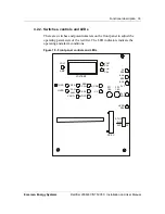
Table 11 - Adjusting the potentiometers and switches
Potentiometers Description
CL ADJ
Current limit adjust ( 100 A to 210 A )
CUR CAL
Current reading calibration
EQL ADJ
Equalize voltage adjust ( 0 V to
−
4 V )
FLT ADJ
Float voltage adjust (
−
46 V to
−
58 V )
HVSD ADJ
High voltage shutdown adjust (
−
52 V to
−
60 V )
VOLT CAL
Voltage reading calibration
Switches Description
EQL / FLT
Equalize / Float selection switch
SLS / FS
Slope load sharing / Forced load sharing selection
ST UP DELAY
Start-up delay selection DIP ( 4 sec to 2 min )
VOLT / AMP
Voltage and current display selection switch
Table 12 - Rectifier input / output signals to the controller
Designation Description
RG+ / RC
−
External reference voltage across the batteries
measured through the controller to regulate the voltage.
HVSD
Remote High Voltage Shutdown input activated by a
BAT RTN signal.
HVSDR
Remote High Voltage Shutdown Reset input activated by
a BAT RTN signal.
TR
Remote Inhibit input activated by a BAT RTN signal.
EQL
Remote Equalize input activated by a BAT RTN signal.
RFA
Rectifier Failure Alarm output activating a form C contact
F ALM
Fan Failure Alarm output activating a form C contact
SHUNT ( + ) and
SHUNT (
−
)
Rectifier Current input / output ( 50 mV / 250 A )
CURRENT
SHARE
Common Forced Current Share Mode ( 0-12 V )
4.2.5. Voltage / current display
test and measurement
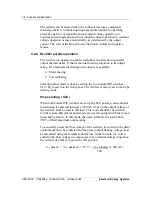
CUR CAL / VOLT CAL potentiometers
These potentiometers are used to calibrate the digital display meter for
current and voltage measurements. As the two potentiometers affect each
other, current calibration must be performed before voltage calibration.


