


EMC
®
VNX
™
Procedure Generator
EMC CONFIDENTIAL
version: 4.5
19 of 51
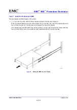
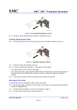
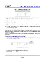
2. [ ] Secure the front of the chassis to the vertical channels of the cabinet using four M5 12.7 mm
screws (two per side) (Figure 7).
CL4138b
Figure 7
Securing the DME to the Cabinet
Transfer Components to the Replacement DME
You must transfer the power/cooling modules, CPU modules, management modules, and I/O modules from
the faulted chassis to the corresponding locations in the replacement chassis. Use the procedures in the
sections that follow to transfer these components.
You must transfer the power/cooling modules and the CPU modules from the faulted chassis to the same
locations in the replacement chassis one component at a time. Transfer components from the A side first
(from the rear of the system, this is the right side), then transfer components from the B side (from the rear
of the system, this is the left side).
For each Blade, starting with the components on the A side (from the front of the system, this is the left side),
complete the following steps, as described in the sections that follow, to transfer the power/cooling modules
and the CPU modules:
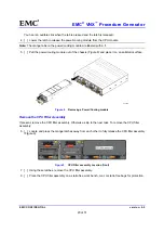
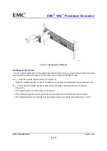
Removing a Power/Cooling module
3. [ ] Locate and press the orange tab on the power/cooling module (Figure 8)


