LPC2478 Developer’s Kit
- User‟s Guide
Copyright 2011 © Embedded Artists AB
EA2-USG-0801 Rev I
User’s Guide
Get Up-and-Running Quickly and Start Developing Your Applications On Day 1!
Страница 1: ...LPC2478 Developer s Kit User s Guide Copyright 2011 Embedded Artists AB EA2 USG 0801 Rev I LPC2478 Developer s Kit User s Guide Get Up and Running Quickly and Start Developing Your Applications On Day 1 ...
Страница 2: ...itten permission of Embedded Artists AB Disclaimer Embedded Artists AB makes no representation or warranties with respect to the contents hereof and specifically disclaim any implied warranties or merchantability or fitness for any particular purpose Information in this publication is subject to change without notice and does not represent a commitment on the part of Embedded Artists AB Feedback W...
Страница 3: ... External Memories 11 3 1 6 External Memory Interface 11 3 1 7 Reset Generation 11 3 1 8 I2C E2PROM 11 3 1 9 Expansion Connectors 12 3 2 Memory Layout 12 3 3 Usage of CPU Pins 12 3 4 LPC2478 OEM Board Mechanical Dimensions and Connector 13 3 5 Known Limitation of LPC2478 OEM Board 14 3 5 1 Ver 1 0 SDRAM Clock Frequency 14 3 5 2 Ver 1 0 Ethernet Clock 14 3 5 3 NAND FLASH Bad Block 14 3 5 4 Brand of...
Страница 4: ...1 Demo Applications 24 5 1 1 Custom Slideshow Demo Application 3 24 5 2 Initial Setup and Powering 26 5 3 Getting Started with uClinux 28 5 3 1 Basic Requirements 28 5 3 2 LAN Ethernet Setup 28 5 4 FTDI USB Driver Installation 30 5 4 1 USB Driver Behavior 33 6 Further Information 34 ...
Страница 5: ... Revision History Revision Date Description A G 2007 2010 Earlier versions of document H 2010 12 10 Updated manual according to new template Removed schematics from document Added known issue with newer SD MMC memory cards requiring pull up resistors I 2011 12 19 Added note about CE marking ...
Страница 6: ...oller in BGA package with 512 KByte program FLASH and 96 KByte SRAM External FLASH memories 128 MB NAND FLASH and 4 MB NOR FLASH External data memory 32 MB SDRAM 32 bit or 16 bit databus width 12 0000 MHz crystal for maximum execution speed and standard serial bit rates including CAN and USB requirements 32 768kHz RTC crystal 100 10M Ethernet PHY interface based on National DP83848 256 Kbit I2C E2...
Страница 7: ...250x150 mm in size 2 2 ESD Precaution Please note that the LPC2478 OEM Board and QVGA Base Board come without any case box and all components are exposed for finger touches and therefore extra attention must be paid to ESD electrostatic discharge precaution Make it a habit always to first touch the metal surface of one of the USB or Ethernet connectors for a few seconds with both hands before touc...
Страница 8: ...ing other devices to the general expansion connectors of the LPC2478 Developers Kit Due to the nature of the LPC2478 Developers Kit an evaluation board not for integration into an end product fast transient immunity tests and conducted radio frequency immunity tests have not been executed Externally connected cables are assumed to be less than 3 meters The general expansion connectors where intern...
Страница 9: ...e 9 Copyright 2011 Embedded Artists AB 2 6 2 OEM Education QuickStart Boards and Kits Visit Embedded Artists home page www EmbeddedArtists com for information about other OEM Education QuickStart boards kits or contact your local distributor ...
Страница 10: ... voltage 3 1 2 Powering There is no internal power supply on the board The LPC2478 contains an internal DC DC converter to generate the internal 1 8V power needed by the core The LPC2478 OEM Board module must be powered by a single external 3 3V power supply The supply must be stable and should have at least four 22uF bulk capacitor s close to the power pins on the expansion connectors 3 1 3 Analo...
Страница 11: ...ntrols the direction of the data bus buffer During read operations the buffer acts as an input and during write operations it acts as an output Note that DBUS_EN must not be pulled low constantly In that case the buffer will collide with the board s internal data bus DBUS_EN must only be pulled low when an external memory IO device is accessed If for example CS2 is used to decode and access an ext...
Страница 12: ... Usage of CPU Pins Almost all pins of the LPC2478 are directly available on the expansion connectors Only in a few cases are pins used for dedicated functionality like Ethernet interface and chip select signals Such pins are not available on the expansion connector The table below lists all pins and their possible restrictions Pin Available on expansion connector P0 0 P0 26 Yes P0 27 P0 28 Yes but...
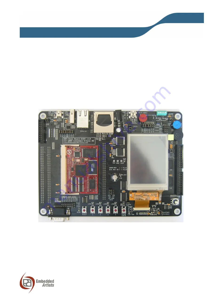
Страница 13: ... devices etc to the LPC2478 OEM Board Study this schematic also found in this document for details 3 4 LPC2478 OEM Board Mechanical Dimensions and Connector Figure 1 below contains a drawing of the board that includes mechanical measures See SODIMM 200 standard for exact measures 1 8V keying is used SODIMM 200 boards are either 1 8V or 2 5V keyed Figure 1 LPC2478 OEM Board Mechanical Dimensions 32...
Страница 14: ...n a maximum cpu clock frequency of 48 MHz when using the external SDRAM If the SDRAM is not used the cpu core frequency can be up to full specification of the LPC2478 3 5 2 Ver 1 0 Ethernet Clock Due to an error in clock routing between the Ethernet PHY and the LPC2478 rev 1 0 boards have been modified slightly The error is also temperature dependent Only a small number of ver 1 0 boards have been...
Страница 15: ...flash and SDRAM The lifetime of memory chips is limited and availability can also be limited from time to time Embedded Artists make every effort to mount the original design chip on the board In case that is impossible a compatible chip will instead be mounted without any prior notice There can be small programming differences between mounted brands The application program shall always read the c...
Страница 16: ...o IrDA transceiver P0 1 Can be connected to TD1 for CAN channel 1 can also connect to IrDA transceiver P0 2 Can be connected to USB to serial bridge TxD on UART 0 P0 3 Can be connected to USB to serial bridge RxD on UART 0 P0 4 LCD databit 0 can also be connected to RD2 for CAN channel 2 P0 5 LCD databit 1 can also be connected to TD2 for CAN channel 2 P0 6 LCD databit 8 P0 7 LCD databit 9 P0 8 LC...
Страница 17: ...al usage on QVGA Base Board P1 18 Connects to QVGA backlight control Can also be connected to LED active low to be used for USB device OTG P1 19 No special usage on QVGA Base Board P1 20 LCD databit 10 P1 21 LCD databit 11 P1 22 LCD databit 12 P1 23 LCD databit 13 P1 24 LCD databit 14 P1 25 LCD databit 15 P1 26 LCD databit 20 P1 27 LCD databit 21 can also be connected to ISP1301 USB OTG transceive...
Страница 18: ...nsceiver active low P2 15 Can connect to interrupt signal from touch screen controller P2 19 Can be connected to Ethernet PHY interrupt output P2 21 Can be connected to NAND FLASH busy output P2 22 Connects to joystick switch P2 23 Connects to joystick switch P2 25 Connects to joystick switch P2 26 Connects to joystick switch P2 27 Connects to joystick switch P2 30 Can control sensitivity of accel...
Страница 19: ...ial usage on QVGA Base Board P4 25 WE buffered signal from cpu board No special usage on QVGA Base Board P4 26 BLS0 buffered signal from cpu board No special usage on QVGA Base Board P4 27 BLS1 buffered signal from cpu board No special usage on QVGA Base Board P4 28 LCD databit 2 P4 29 LCD databit 3 VBAT 0 33F backup cap on vbat signal ALARM Connected to alarm LED active high VREF Can be connected...
Страница 20: ...onnect V3A to VREF and trimpot to analog AD0 2 Accelerometer J12 Connect xyz to AD0 0 AD0 2 Enable ETM J10 No of disp colors J30 J31 J32 All to left 16 bit color interface to display All to right 24 bit color interface Enable JTAG J6 NAND Busy and Ethernet PHY J7 Top Connect Nand busy signal to P2 2 Bottom Connect Ethernet PHY PD signal to P2 19 LCD Enable J33 Enable power switch to display Int ex...
Страница 21: ...usive and should not be inserted simultaneously USB OTG and LCD interface the four jumpers in J25 should not be inserted when using the LCD interface since signals P1 27 P1 29 are also connected to the ISP1301 When using the 32 bit data bus version of the LPC2478 OEM Board all jumpers in connectors J20 should always be removed Also J23 J24 should not be in upper position The UART signals in signal...
Страница 22: ...is not mounted on the board It s designated J6 The connector can be soldered to the board if needed The connector is from Tyco Electronics Amp and is a 38 way receptacle Mictor connector 0 025 pitch part number 767054 1 or 2 5767004 2 RoHS compliant SD MMC J9 USB to serial J15 Input power J13 CAN J17 Display Expansion J36 RS232 J21 Expansion connector J1 J2 JTAG J5 ETM J8 not mounted Ethernet J4 U...
Страница 23: ...nts in the design Figure 6 QVGA Base Board Important Components SD MMC LEDs power inserted write protected USB to serial activity LEDs Reset push button and Reset LED Joystick SW7 Voltage measurement pads and Power LED LED15 Trimpot for analog input SW2 SW5 marked KEY1 4 LED6 13 marked LED1 8 on pcb P2 10 push button SW6 Trimpot for speaker output volume Accelerometer Speaker IrDA transceiver ...
Страница 24: ... 11 Touch screen calibration 12 About information Select which demo application to start by tapping on the screen i e via the touch screen interface or moving around with the joystick switch Please note that source code is not available for the demo applications The demo illustrates the capabilities of the processor and Embedded Artists as a software provider See our sample application package for...
Страница 25: ...ontain exactly one command No more than 40 images may be loaded at the same time The available commands are load filename slot Loads the image file into memory in the specified slot The slot number is zero indexed and there are 40 slots Remember that each loaded image will occupy 230x320x3 bytes of RAM clear Clears the screen by setting all pixels white label name Creates a label that can be refer...
Страница 26: ...mber of effects to apply when transitioning from the old image to the new The following transitions are available in the demo none left right top down blinds explode_v explode_h 5 2 Initial Setup and Powering The board can be powered from a PC via the included USB cable mini B to A cable A separate power supply is however needed in stand alone situations or when running USB Host application when p...
Страница 27: ...or the virtual COM port to be created See Section 5 4 for a description of how to install the FTDI USB driver There are four jumpers on the QVGA Base Board related to the USB serial channel connected to UART 0 of the LPC2478 See Figure 8 below for details about where the jumpers are located Make sure the automatic ISP jumpers are open If not it s possible that a terminal program resets the board a...
Страница 28: ...first step is to download the uBoot bootloader into the LPC2478 internal flash memory This can be downloaded either via ISP or via the JTAG interface The uBoot bootloader hex file can be downloaded from the board s support page This guide is just a quick guide you get to take the first step and start using the board More detailed information can be found on the board s support page 5 3 1 Basic Req...
Страница 29: ... as your PC An IP address starting with 192 168 0 x is a common IP subnet for many PCs If this does not match your PC either change the IP address of your PC or change the IP address of the LPC2478 OEM Board see description of this at the last section of this page Make sure your PC does not have the IP address 192 168 0 100 but any other IP address in the range 192 168 0 X where X is 1 99 101 254 ...
Страница 30: ...m Also see FTDI s installation guides for details how to install the driver for different operating systems http www ftdichip com Support Documents InstallGuides htm When the QVGA Base Board is connected to the PC via an USB cable the PC will ask for a driver Unpack unzip the downloaded driver file and browse to the position of the driver files After successful driver installation a COM port will ...
Страница 31: ...rt and select Properties as illustrated in Figure 12 below Figure 12 Device Manager Port Dialog Set 115200 or 38400 bits per second 8 data bits none parity 1 stop bit and none flow control as illustrated in Figure 13 below Select 115200 bps is connecting to the demo program and 38400 if working with uClinux Then select Advanced settings Please note that different application programs Ports USB Ser...
Страница 32: ...often the COM port number selected but the USB Serial Port is higher than this so this needs to be changed manually It is common that all COM ports with low numbers are listed as occupied but test to change to a low number anyways Very often it s no problem at all to do this Figure 14 Advanced USB Serial Port Properties Dialog Finally it s time to test if you have successfully installed and config...
Страница 33: ...numerate properly when the board in connected to the PC This is a known feature of the USB driver If you experience this problem just unplug the board shortly and then plug in again A new COM port that can be accessed properly should be created the second time This problem may occur after every time you start i e power cycle your PC If the ISP jumpers are inserted pressing the reset button is ofte...
Страница 34: ...BN 0 201 73719 1 Also available in PDF form on the ARM Technical Publications CD 6 ARM System Developer s Guide Designing and Optimizing System Software by A N Sloss D Symes C Wright Elsevier ISBN 1 55860 874 5 7 Embedded System Design on a Shoestring by Lewin Edwards Newnes ISBN 0750676094 8 GNU Manuals http www gnu org manual 9 GNU ARM tool chain for Cygwin http www gnuarm com 10 An Introduction...
Страница 35: ... SAFETI HSK RM48 LS1024A RDB ADM00573 FRDM KL28Z PICOHOBBITFL MCIMX53 START R TWR K65F180M KEA128BLDCRD CC ACC MMK 2443 STM8L1528 EVAL YSPKS5D9E10 YGRPEACHFULL TWR MC FRDMKE02Z TWR K80F150M CY14NVSRAMKIT 001 EVALSPEAR320CPU EVB SCMIMX6SX MAXWSNENV FM0 64L S6E1C3 MAX32600 KIT TMDX570LS04HDK Z32F3840100KITG LS1021A IOT B SK FM3 100PMC MB9BF516N TXSD SV70 YSTBS3A3E10 YR8A77430HA02BG STM3240G USB NMF ...