7
LAN
Alimentazione
MIC
HP
Alm_GND
Alm_IN
LAN
Alimentazione
MIC
HP
LAN
MIC
HP
Alm_NO
Alm_COM
RS485-
RS485+
Alm_GND
Alm_IN
Alm_NO
Alm_COM
RS485-
RS485+
Modem
Switch
LAN
Internet
Modem
Allarme
PTZ
Switch
LAN
Internet
Sensore
Modem
Allarme
PTZ
Tastiera
Switch
LAN
Internet
Sensore
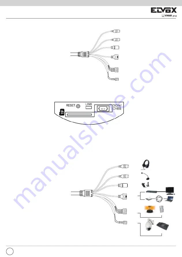
2.2 Interfaces and Connections: for camera with connection of alarm infant, RS485 TF card
- Connections of the external ports:
HP: Connect to headphone.
MIC: Connect to microphone.
DC12V: Power supply port.
LAN: Network port. It supports PoE power supply.
Alarm NO/COM: Alarm output. Conect to alarm output devices.
Alarm GND: Connect to external sensor together with the alarm in line.
Alarm IN: Connect to alarm input devices, like senor, together with alarm GND line.
RS485: Connect to keyboard or speed doom.
- Connections of the internal ports
)RFXV
=RRP
Manuale per l’installazione e l’uso
Installation and operation manual
46226.212
Telecamera Dome IR IP full HD, obiettivo 2,8-12 mm
Camera Dome IR IP full HD, Lens 2,8-12 mm
You shall take down the back box of the device if you want to see the above ports.
Link: Network indicator.
RESET: Reset hole. Hold and press the spring blade in this hole with spicule to reset the settings to the factory default settings.
TF: Insert TF card.
DCIN/CVBS: Connect to a 3 pin joint which has a power supply port and a CVBS port in the other end. You can connect to
monitor for video adjustment.
User can connect the PC and IP-CAMERA in accordance with the above picture. Before connecting, please connect external
devices, and then connect the power.
EN
Power supply
3 Installation
3.1 Connect IP-CAMERA to Network
The connection of IP-CAM is shown below:
LAN
Alimentazione
MIC
HP
Alm_GND
Alm_IN
LAN
Alimentazione
MIC
HP
LAN
MIC
HP
Alm_NO
Alm_COM
RS485-
RS485+
Alm_GND
Alm_IN
Alm_NO
Alm_COM
RS485-
RS485+
Modem
Switch
LAN
Internet
Modem
Allarme
PTZ
Switch
LAN
Internet
Sensore
Modem
Allarme
PTZ
Tastiera
Switch
LAN
Internet
Sensore
HP
MIC
LAN
Power supply
Alarm
Sensor
Keyboard


