background image

____________________________________________________________________________________ 

____________________________________________________________________________________


            NTU Optical Network Terminals


65


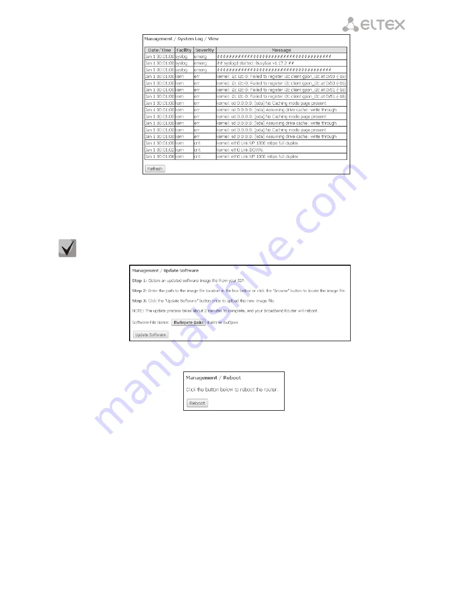
Click 

Close

 to close the log display window.


Use the 

Refresh

 button to refresh the information.  

4.6.7


The Update Software Submenu. Software Update


To update software, select the software in the 

Software File name 

field (use the 

Choose a File

 or 

Browse


buttons) and click 

Update Software.


Do not switch off or reboot the device during the update. The process may take several minutes. The 
device will be automatically rebooted when the update is completed. 


4.6.8


The Reboot Submenu.


Device Reboot


Click the 

Reboot

 button to reboot the device. The device reboot may take several minutes.


Содержание NTU-2C

Страница 1: ...NTU 2V C NTU 2W NTU RG 1402G W Operation Manual Version 1 0 17 April 2017 Optical Network Terminals IP address http 192 168 1 1 User name user Password user http eltex co ru support downloads ...

Страница 2: ... Network Terminals Document version Suitable firmware version Issue date Changes Version 1 0 3 25 2 1593 17 April 2017 First issue NOTES AND WARNINGS Notes contain important information tips or recommendations on device operation and setup Warnings inform users about hazardous conditions which may cause injuries or device damage and may lead to the device malfunctioning or data loss ...

Страница 3: ... Device General Information 34 4 1 2 The WAN Submenu The Status of Services 34 4 1 2 1 The Detail Submenu Detailed Information 35 4 1 3 The LAN Submenu LAN Ports Monitoring Wi Fi Interface Status Monitoring 35 4 1 4 The Statistics Submenu Traffic Flow Information for Ports of the Device 35 4 1 5 The Route Submenu The Routing Table 37 4 1 6 The ARP Submenu ARP Protocol Cache 38 4 1 7 The DHCP Subme...

Страница 4: ... Bridge Mode 58 4 4 5 The Advanced Submenu Advanced Settings 58 4 5 Storage Service menu File Storage Service 60 4 5 1 Storage Device Info submenu Connected USB Device Info 60 4 5 2 User Accounts submenu Configuration of Samba users 61 4 6 The Management menu Device Management 61 4 6 1 The Setting submenu Settings 61 4 6 1 1 The Backup submenu Backup 61 4 6 1 2 The Update submenu Configuration Upd...

Страница 5: ... Ethernet and GPON interfaces and is used to connect a PON network with data communication networks of a higher level ONT is designed to connect user terminal equipment to broadband access services It can be used in residential areas and office buildings The range of ONT NTU equipment produced by Eltex comprises of the following terminals NTU 2V C with two Ethernet user network interfaces UNI 1 Et...

Страница 6: ...acket filtering for access control based on ports and source destination MAC IP addresses Users can configure home or office websites by adding one of the LAN ports to the DMZ Parental Control feature filters out websites with unwanted content block domains and defines the Internet usage schedule Virtual private network VPN provides mobile users and branch offices with a protected communication ch...

Страница 7: ...P CHAP MSCHAP authentication static IP address and DHCP DHCP client on WAN side DHCP server on LAN side UPNP IPSec NAT Firewall NTP QoS IGMP snooping IGMP proxy Parental Control VoIP SIP audio codecs G 729 A G 711 A U G 723 1 ToS for RTP packets ToS for SIP packets echo cancellation G 164 and G 165 guidelines silence detector VAD comfortable noise generator DTMF signal detection and generation DTM...

Страница 8: ...VC 2 3 2 NTU 2W The device has the following interfaces 1 PON SC APC port for connection to operator s network Ethernet RJ 45 LAN ports for connection of network devices 1 RJ 45 10 100 Base T port 1 RJ 45 10 100 1000Base T port 1 Wi Fi transmitter receiver 802 11b g n 1 USB 2 0 port for external USB or HDD storages The terminal uses an external adapter for 220V 12V power supply The device supports...

Страница 9: ...shows a diagram of the NTU 2W equipment application diagram Fig 2 Application diagram of NTU 2W 2 3 3 NTU RG The device has the following interfaces 2 RJ 11 ports for connection of analogue phones 1 PON SC APC port for connection to operator s network 4 Ethernet LAN RJ 45 10 100 1000Base T ports for connection of network devices 1 Wi Fi transmitter receiver 802 11b g n 2 USB 2 0 ports for external...

Страница 10: ...s Echo cancellation G 164 and G 165 guidelines Silence detector VAD Comfortable noise generator DTMF signal detection and generation DTMF transmission INBAND RFC2833 SIP INFO Fax transmission upspeed pass through G 711 T 38 Value Added Services VAS Call Hold Call Transfer Call Waiting Forward unconditionally Forward on no answer Forward on busy Caller ID Display for ETSI FSK Anonymous calling Warm...

Страница 11: ...ce Number of interfaces NTU 2V C 2 NTU 2W 2 NTU RG 1402G W 4 Socket RJ 45 Data transfer rate Mbps Autodetection 10 100 1000 Mbps Duplex half duplex Standards IEEE 802 3i 10Base T Ethernet IEEE 802 3u 100Base TX Fast Ethernet IEEE 802 3ab 1000Base T Gigabit Ethernet IEEE 802 3x Flow Control IEEE 802 3 NWay auto negotiation Parameters of PON Interface Number of PON interfaces 1 Standards ITU T G 984...

Страница 12: ... g n Frequency range 2 400 2 497 GHz Modulation PSK CCK DQPSK DBPSK OFDM Data transfer rate Mbps 802 11b 11 5 5 2 1 802 11g 54 48 36 24 18 12 9 6 802 11n 20MHz BW 130 117 104 78 52 39 26 13 802 11n 40MHz BW 270 243 216 162 108 81 54 27 Maximum transmitter output power 802 11b 17dBm 1 5dBm 802 11g 15dBm 1 5dBm 802 11n 14 75dBm 1 5dBm 802 11ac 5 GHz 19 dBm МAС protocol CSMA CA model of ACK 32 MAC Se...

Страница 13: ... 1402G W 0 3 kg 2 5 Design 2 5 1 NTU 2V NTU 2V devices are designed as 122 96 32 mm desktop device in a plastic housing The figure 4 shows the NTU 2V rear panel layout Fig 4 NTU 2V Rear Panel The connectors and controls located on the rear panel of NTU 2V are shown in the table Table 3 Description of the LEDs and Controls Located on the Rear Panel Rear Panel Element Description 1 12V Power adapter...

Страница 14: ...ls are shown in table Table 4 Description of the LEDs and Controls Located on the Rear Panel Panel Element Description 5 Power Device power and activity status indicator 6 Status Device authentication indicator 7 Analogue phone indicator 8 LAN Ethernet ports activity indicators 9 PON Optical interface indicator 10 Reset A functional key that reboots the device and resets it to factory settings 2 5...

Страница 15: ...cription 1 On Off Power supply button 2 12V Power adapter connector 3 F a functional key that reboots the device and resets it to factory settings 4 RF port TV set connector for CaTV 5 LAN 10 100 1000 1 LAN 10 100 1000 2 2 RJ 45 ports for connection to network devices 6 Phone RJ 11 port to connect network devices 7 PON SC port socket for PON with GPON interface Fig 7 shows a NTU 2V side and front ...

Страница 16: ...dicator 2 5 3 NTU 2W NTU 2W devices are designed as 147 110 24 mm desktop device in a plastic housing The Fig 8 shows the NTU 2W rear panel layout Fig 8 NTU 2W Rear Panel The connectors and controls located on the rear panel of NTU 2W are shown in the table Table 7 Description of the LEDs and Controls Located on the Rear Panel Rear Panel Element Description 1 LAN 100 RJ 45 100Base TX port for conn...

Страница 17: ...Description of the LEDs and controls located on the side and top panels replace the names with corresponding icons Panel Element Description 1 Power indicator 2 Device configuration and firmware status indicator 3 USB operation indicator 4 Optical interface indicator 5 Optical interface error indicator 6 Internet connection indicator 7 Wi Fi activity indicator 8 WPS operation indicator 9 1 2 Ether...

Страница 18: ...device in plastic housing The Figure 10 shows the NTU RG 1402G W rear panel layout Fig 10 NTU RG 1402G W Rear Panel layout The connectors and controls located on the rear panel of NTU 2W are shown in the table Table 10 Description of the LEDs and Controls Located on the Rear Panel Rear Panel Element Description 1 On Off Power supply button 2 12V Power adapter connector 3 PON SC port socket for PON...

Страница 19: ...or 8 Status Device authentication indicator 9 PON Optical interface indicator 10 Wi Fi Wi Fi activity indicator 11 1 2 FXP port activity indicators 12 LAN 1 4 Ethernet ports activity indicators See table 12 for detailed information about LEDs located on the top panel of the device Table 12 Description of front panel LED indicators Side Panel Element Description 13 Reset a functional key that reboo...

Страница 20: ...ly authenticated on line terminal PPP session started in WAN interface orange device is not authenticated PPP session is not started in WAN interface Power off device is disconnected from the power source or faulty green current device configuration differs from the default one orange the default configuration is active red device booting 2 6 2 NTU 2VC The LED indicators located on the front panel...

Страница 21: ...es of the LEDs Table 15 Light Indication of Device Status LED LED Status Device Status 1 off the device is disconnected from the power source or faulty green power on 2 orange the default configuration is active green a non default configuration flashes green updating firmware 3 off no USB device is connected green USB device is connected flashes green accessing the USB device 4 off optics is not ...

Страница 22: ...al flashes red no signal from optical line terminal Status off WAN interface is in static or bridge mode PPP client is not running green device was successfully authenticated on line terminal PPP session started in WAN interface orange device is not authenticated PPP session is not started in WAN interface Power off the device is disconnected from the power source or faulty red device booting oran...

Страница 23: ...to combine LAN ports into a single group The eth0 1 blocks physically represent Ethernet ports with RJ 45 connector for connection of PC STB or other network devices They are logically included into the br1 block FXS blocks are ports with RJ 11 connectors for connection of analogue phones They are logically included into the Voice block The Voice block can be controlled through a web interface or ...

Страница 24: ...of gem ports that are used for transmitting traffic of various services The GEM4094 block is a logical terminal of the GEM port used for multicasting It multicasts traffic downstream WAN Connection Device receives the multicast traffic from this block and sends it further to Bri interfaces based on the table of IGMP groups The bronu0 9 blocks are MAC bridge service profiles recommendation G 988 Th...

Страница 25: ...e the interface into one group The br1 block is connected to the veip0 1 interface which operates in the PPPoE mode and to the eth0 port The br4 block operates in bridge DHCP mode in order to use the address of this interface for SIP client Voice block The br2 br5 br6 blocks operate as a bridge which allows transparent traffic transmission to the LAN ports of the router The eth0 1 blocks represent...

Страница 26: ...ts in one group The eth0 1 blocks physically represent Ethernet ports with RJ 45 connector for connection of PC STB or other network devices They are logically included into the br1 block The wl0 block is an interface for Wi Fi module connection The Filter and Marking blocks are designed to include local interfaces in one group br1 These blocks are responsible for traffic rules Filter is used for ...

Страница 27: ...ces based on the table of IGMP groups The bronu0 9 blocks are MAC bridge service profiles recommendation G 988 The TR 069 client block is used for device remote control with the help of the ACS server Auto Configuration Server via TR 069 protocol The block is used to establish communication between ACS and subscriber s equipment process ONT queries and configure services The WANConnectionDevice bl...

Страница 28: ...operates in the PPPoE mode and to the eth0 port The br2 br3 blocks operate as a bridge which allows transparent traffic transmission to the LAN ports of the router The eth0 1 blocks represent LAN interfaces for connection of subscriber s equipment Fig 17 Architecture of the Device Configured for Triple Play Model 2 Services The difference between the models is the GEM4095 block which is a logical ...

Страница 29: ... block eth0 3 FXS0 1 wl0 IPInterface In this case the br1 block is used to combine LAN ports in one group The eth0 3 blocks physically represent Ethernet ports with RJ 45 connector for connection of PC STB or other network devices They are logically included into the br1 block FXS0 1 blocks are ports with RJ 11 connectors for connection of analogue phones They are logically included into the Voice...

Страница 30: ...nsures connection of the subscriber s ONT device to station side equipment Fig 19 Architecture of the Device Configured for Triple Play Model 1 Services The blocks created by the OMCI protocol during connection to OLT left are shown for clarity and do not describe the real architecture The gemport blocks represent logical terminals of gem ports that are used for transmitting traffic of various ser...

Страница 31: ...for the Internet veip0 2 controls the multicast traffic Veip0 3 provides VoIP services veip0 4 provides VPN service on a separated port veip0 5 provides other services alarm system veip0 6 provides VoD and IPTV on STB These WAN interfaces have the following operation modes PPPoE starts PPP client IPoE DHCP starts DHCP client IPoE Static uses a static address Bridging operates in the bridge mode Th...

Страница 32: ...al Network Terminals Fig 20 Architecture of the Device Configured for Triple Play Model 2 Services The difference between the models is the GEM4095 block which is a logical terminal of the GEM port for broadcasting It broadcasts traffic downstream Broadcast packets are sent from the GEM4095 block to WAN Connection Device and then are further transmitted to bri according to VLAN ID ...

Страница 33: ... To do this enter the device IP address into the address bar of the web browser the factory default IP 192 168 1 1 subnet mask 255 255 255 0 When the IP address is entered the device will request a user name and a password User name user password user To prevent unauthorised access to the device we recommend to change the password see section 4 6 5 The Passwords Submenu Access Control Settings pas...

Страница 34: ...ial number of the device in the PON network Base WAN MAC WAN MAC address of the device Board ID board identification number Hardware Version version of the hardware installed Software Version version of the firmware installed Bootloader CFE Version version of the bootloader installed Wireless Driver Version1 Wi Fi adapter version System time the current time settings of the device Uptime time from...

Страница 35: ...us connection status IPv4 Address access address Default Gateway the default gateway Primary DNS Server1 address of the primary DNS server used for work Secondary DNS Server1 address of the secondary DNS server Bridging to list of the linked LAN interfaces 4 1 3 The LAN Submenu LAN Ports Monitoring Wi Fi Interface Status Monitoring Status and parameters of wired and wireless LAN interfaces are ava...

Страница 36: ..._______________________________________________________ ____________________________________________________________________________________ 36 NTU Optical Network Terminals LAN interface NTU 2V C NTU 2W NTU RG 1402G W WAN Service ...

Страница 37: ...level of the outgoing signal 1310 nm Temperature temperature of the SFF module Vcc Voltage power voltage Bias Current offset current To clear the statistics and start gathering it again click the Reset Statistic button 4 1 5 The Route Submenu The Routing Table The menu shows the routing table Destination IP address of the destination Gateway IP address of the gateway Subnet mask subnet mask Genmas...

Страница 38: ...te active client Incomplete the client is not responding to ARP requests HW Address МАС address of the client Device the interface where the client is located on 4 1 7 The DHCP Submenu Active DHCP Leases The DHCP table provides a list of active DHCP leases and their duration Hostname host name network device MAC Address MAC address of the device IP Address LAN address of the device chosen by the r...

Страница 39: ... section shows a list of detected wireless networks The device information is shown in a table with the following parameters SSID name of the wireless network BSSID MAC address of the access point Channel channel of the access point RSSI level of the signal sent by the access point and received by the ONT Click the Refresh button to refresh the data 4 1 10 Voice submenu2 Monitoring the phone port ...

Страница 40: ... The Advanced Setup Menu Advanced Settings 4 2 1 The LAN Submenu Configuration of Main Parameters The menu allows configuration of the main parameters of the LAN interface IP Address address of the device in local network Subnet Mask subnet mask DHCP Server Dynamic Host Configuration Protocol allows you to configure local computers automatically in order to work in a network DHCP server automatica...

Страница 41: ...he PPPoE_Bridged mode The username and password are entered on user PC Click the Apply Save button to accept and save the changes 4 2 3 The NAT Submenu NAT Settings NAT settings can be useful when the device operates in the router mode 4 2 3 1 The Virtual Servers Submenu Settings of Virtual Servers Virtual Server is a router function which provides users with Internet access to the servers located...

Страница 42: ...nal port of the port range accessible from the Internet External Port End the last external port of the port range accessible from the Internet Protocol select a network protocol Internal Port Start the first internal port of the port range to receive forwarded traffic from an external port of the router Internal Port End the last internal port in the port range to receive forwarded traffic from a...

Страница 43: ...Select an application select a preconfigured rule Custom an application create custom rules not listed in the Select an Application list As opposed to the Virtual Server function you don t need to specify a fixed IP address of the computer in LAN Trigger Port Start the first port of the port range to act as a trigger Trigger Port End the last port of the port range to act as a trigger Trigger Prot...

Страница 44: ...host with a specific address in LAN Delete the IP address in the field to disable this option Click the Apply Save button to accept and save the changes 4 2 4 The Security Submenu Security Settings This submenu allows configuration of device security settings 4 2 4 1 The IP Filtering Submenu Addresses Filtering Configuration The IP Filtering function filters the traffic forwarded to IP addresses a...

Страница 45: ...ter a slash Destination Port port or port port destination port or port range separated by a colon Click the Apply Save button to accept and save the settings Filtration Settings for Incoming Traffic When a firewall is enabled in a WAN or LAN interface it blocks all incoming traffic which does not meet the set rules Click the Add button to add a new filtration rule Filter Name text description of ...

Страница 46: ...resses Use MAC Address Filtering to forward or block traffic depending on the source destination MAC addresses MAC address filtering works only for interfaces in the Bridge mode To change the global policy set a flag in front of the corresponding interface and click the Change Policy button Two options are available FORWARDED and BLOCKED In the FORWARDED mode the created rules will block the traff...

Страница 47: ... network at a definite time Click the Add button to create a new schedule You can add up to 16 records User Name user name Browser s MAC Address MAC address which is automatically identified for the computer the schedule is set for Other MAC Address xx xx xx xx xx xx MAC address which is manually defined for the computer the schedule is set for Days of the week days of the week when Internet acces...

Страница 48: ...he Apply Save button to add settings to the table 4 2 6 The Dynamic DNS menu The Dynemic DNS settings Dynamic DNS dynamic domain name system allows DNS server information to be updated in real time and optionally automatically It is used to assign a fixed domain name to a device computer or router e g NTP RG with a dynamic IP address This dynamic IP address can be obtained through IPCP in PPP conn...

Страница 49: ...rg DynSIP org No IP com dnsomatic com sitelutions com Custom any other provider selected by the user In this case the user will need to specify manually the provider s name and address Username user name for the DDNS account Password password for the DDNS account DDNS Provider Server Name name of the DDNS service provider DDNS Provider URL address of the DDNS service provider Hostname host name re...

Страница 50: ...ly Save button to accept and save the changes 4 2 7 Print Server menu1 Print Server Configuration The print server is a software or hardware solution that allows users of wired or wireless networks to share a printer at home or at an office The printer is completely independent from network computers and decreases the load on the user s working environment Besides the print server establishes cont...

Страница 51: ...ction SIP domain name SIP domine name VoIP Dialpan Setting dialplan configuration recommended to use x T Use SIP Proxy when checked SIP Proxy is used SIP Proxy SIP Proxy address SIP Proxy port SIP Proxy port Use SIP Outbound Proxy when checked use SIP Outbound proxy to transmit all requests otherwise SIP Outbound proxy is not used SIP Outbound Proxy SIP proxy address which will be used to transfer...

Страница 52: ...mount of voice data transmitted by one RTP packet in milliseconds Preferred codec select the preferred codec 1 with the highest priority To accept and save settings click the Apply Save button 4 3 2 SIP Advanced Settings submenu Use this submenu to configure Value Added Services for more detailed description see APPENDIX B VALUE ADDED SERVICES USAGE SIP Account SIP account FXS port number Call wai...

Страница 53: ...onymous calling when checked calls from port number are not indentified Caller Identity Restriction service DND when checked Do Not Disturb service is enabled To accept and save the settings click the Apply Save button To apply the new settings stop SIP client by clicking Stop SIP client button and start SIP client again by clicking Start SIP client button 4 4 The Wireless Menu1 Wi Fi Network Setu...

Страница 54: ...ssia Max Clients the maximum possible number of simultaneously supported wireless connections Click the Apply Save button to accept the changes 4 4 2 The Security Submenu Security Settings The menu contains main parameters of data encryption in the wireless network The client wireless equipment can be configured either manually or automatically with the help of WPS WPS Wi Fi Protected Setup is a s...

Страница 55: ...PA and WPA2 encryption protocols It involves bruteforcing of the 8 digit network key PIN code Manual Setup AP Select SSID select a name of a wireless network from the list Network Authentication select a network authentication mode from the drop down list open without wireless network security features only WEP key can be used in this mode Shared this mode enables user authentication by their SSID...

Страница 56: ...WPA2 WPA includes a combination of WPA2 WPA this encryption mode requires a RADIUS authentication server and uses WPA2 and WPA protocols WPA2 Preauthentication pre authentication of the wireless client in other wireless access points in the specified range Connection is established at the current wireless access point during the verification Network Re auth Interval time interval for repeated auth...

Страница 57: ...2 Make sure that the PC s wireless adapter supports the selected encryption type The most secure protection of a wireless channel is reached by the joint operation of access point and RADIUS server for authentication of wireless clients WEP Encryption select Enable in the drop down list to enable WEP encryption Encryption Strength 64 or 128 bit key encryption Current Network Key the key that will ...

Страница 58: ...ireless bridge Using the bridge mode requires MAC addresses of remote bridges to be specified The mode is used for wireless connection between two independent networks The Wireless Bridge mode has the following settings Bridge Restrict select a bridge operation mode Enabled enable the MAC address filter allowed are only the specified addresses Enable Scan search for remote bridges Disable no restr...

Страница 59: ...to channel is selected enter 0 to disable Auto Channel Set defines a channel autoselection mode Full autoselection scans all available channels to choose one Legacy autoselection scans a set of channels supported by old devices for 2 4 GHz range only to choose one Custom austoselection scans channels from the list specified by user in the Allowed Channel settings and chooses one 802 11n EWC compat...

Страница 60: ...ch the broadcast and multicast packets in the buffer will be delivered to wireless clients Beacon Interval time period for transmission of informational packets which indicate activity of the access point to the wireless network Global Max Clients maximum possible number of wireless clients XPress Technology provides an increase in throughput in 802 11g networks up to 27 XPress Technology can incr...

Страница 61: ...n Username username to access a network resource Password password to access a network resource Confirm Password access password confirmation VolumeName path to the network resource name of the connected storage is displayed in the Storage Device Info tab 4 6 The Management menu Device Management 4 6 1 The Setting submenu Settings 4 6 1 1 The Backup submenu Backup Use the Backup Settings button in...

Страница 62: ...al network To change the password enter 10 characters in the New PON Password field Click the Apply Save button to accept and save the changes The settings will be applied after device restart We do not recommend to change the password as the link to the station side device may be lost in this case 4 6 3 Internet Time Submenu System Time settings The tab contains settings for the device system tim...

Страница 63: ...eck availability of the network devices connected to the router To test the availability of the connected device enter its IP address into the field and click the Ping button Click the TraceRoute button to view the route tracing Results will be displayed at this page of web configurator 4 6 5 The Passwords Submenu Access Control Settings password settings Use this submenu to change the device acce...

Страница 64: ...local all events return to the router via the internal buffer Remote remote all events return to Syslog server Both both modes are enabled Flash sends events to a USB drive Linux Level Console Display Level printk set the Linux console logging level Send CMS logs to syslog require reboot enables disables CMS messages transmission to the system log The following settings are available in the Remote...

Страница 65: ...formation 4 6 7 The Update Software Submenu Software Update To update software select the software in the Software File name field use the Choose a File or Browse buttons and click Update Software Do not switch off or reboot the device during the update The process may take several minutes The device will be automatically rebooted when the update is completed 4 6 8 The Reboot Submenu Device Reboot...

Страница 66: ...ascript in the web browser or use another web browser Defective cable Check the physical connection by checking status LEDs all LEDs should be on If the LEDs are off use another cable or connect to another port of the device if available If your computer is switched off LEDs may also be off Access is denied by some Internet security software installed on your PC Disable the Internet security softw...

Страница 67: ...isconnection of subscriber B the subscriber providing the service Service usage While being connected to the subscriber A hold the call by pressing the flash release R wait for the station response signal and dial the subscriber C When the subscriber C answers your call hang up 3 Conference Conference is a service allowing three and more subscribers to have shared phone conversation The service ca...

Страница 68: ...ing The service allows phone access restriction to a certain types of outgoing calls The service can be configured in the menu with user port settings in the VoIP SIP Advanced Setting tab see section 4 3 2 SIP Advanced Settings submenu by setting the Call barring flag and specifying the required parameters in the Call barring mode and Call barring digit map fields Three options of calls restrictio...

Страница 69: ... Equipment shipping and storage should be performed in accordance with GOST 15150 Conditions 5 and Conditions 1 respectively The manufacturer Eltex Ltd guarantees that the subscriber gateway meets the requirements of technical specification TU6650 100 33433783 2013 provided its operation conditions correspond to the ones set forth in this Manual Warranty period 1 year Manufacturing date see on the...

Страница 70: ...ipping and storage should be performed in accordance with GOST 15150 Conditions 5 and Conditions 1 respectively The manufacturer Eltex Ltd guarantees that the subscriber gateway meets the requirements of technical specification TU6650 100 33433783 2013 provided its operation conditions correspond to the ones set forth in this Manual Warranty period 1 year Manufacturing date see on the package The ...

Страница 71: ...hipping and storage should be performed in accordance with GOST 15150 Conditions 5 and Conditions 1 respectively The manufacturer Eltex Ltd guarantees that the subscriber gateway meets the requirements of technical specification TU6650 100 33433783 2013 provided its operation conditions correspond to the ones set forth in this Manual Warranty period 1 year Manufacturing date see on the package The...

Страница 72: ...ipping and storage should be performed in accordance with GOST 15150 Conditions 5 and Conditions 1 respectively The manufacturer Eltex Ltd guarantees that the subscriber gateway meets the requirements of technical specification TU6650 100 33433783 2013 provided its operation conditions correspond to the ones set forth in this Manual Warranty period 1 year Manufacturing date see on the package The ...

Отзывы: