Chapter 5
Installation
tinnerman-style clips and the thermostat “wire” should be attached to the front wall with
clips to prevent damage from vibration.
5.5 Wiring
Before you begin wiring, check that the power switch to the heater is off and the trailer
has no power.
Mount the control box and, if present, the 110 V standby on the trailer in a location where
they may be easily accessed without being exposed to the full force of the wind and
weather. The boxes and associated wiring must not obstruct the propane system that will
be mounted next. In order to make both the installation of both the electrical and propane
system as easily as possible, it is recommended that the electrical components be
mounted toward the right side of the front wall (when facing the outside front wall of the
trailer) and the propane system be mounted on the left side. The control box should be
mounted with the wires exiting on the sides and the 110V standby should be mounted
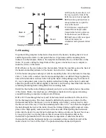
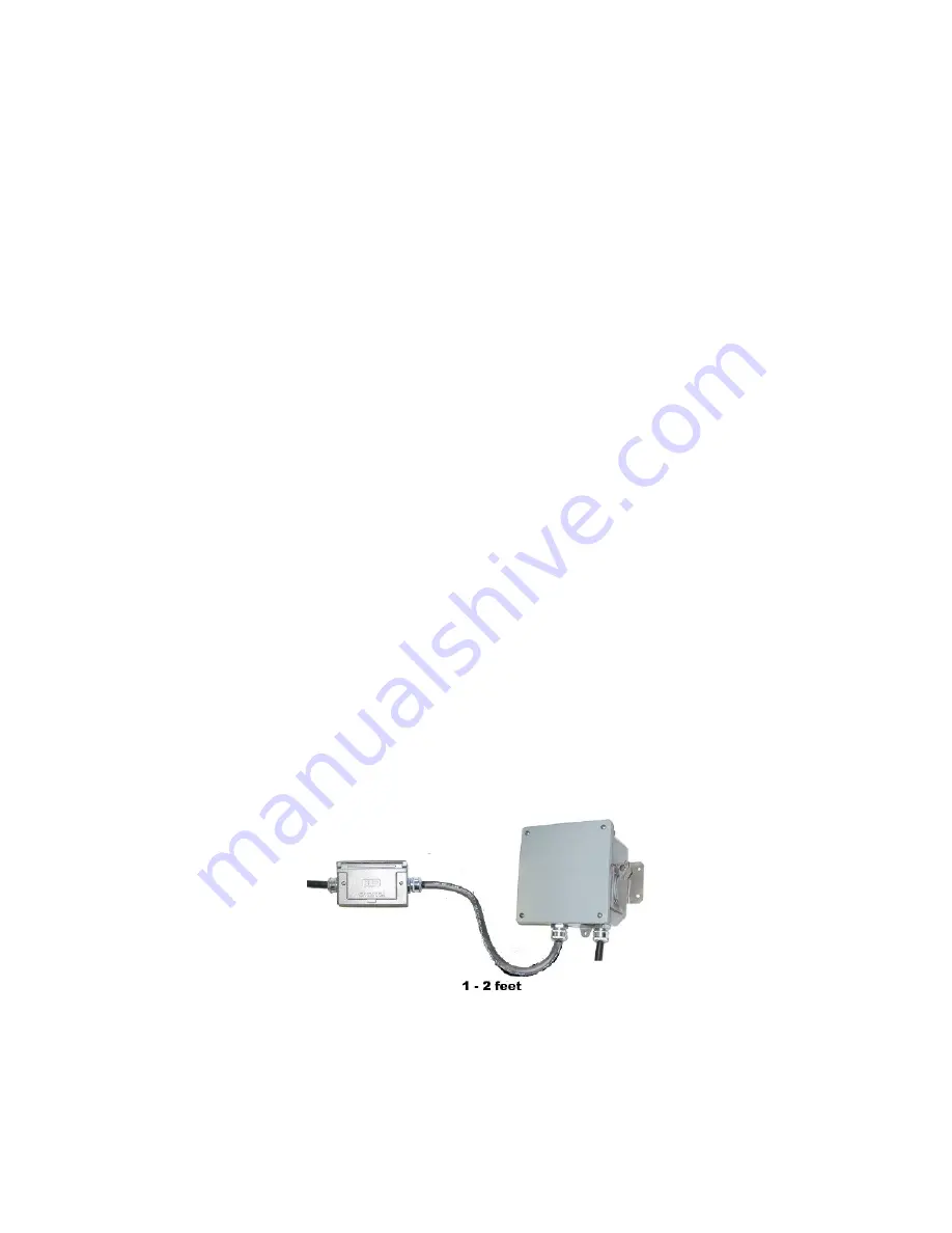
with the wires exiting out of the bottom. (See Figure 7.) There should be a dip in the wire
on both sides of the control box so water running down the wire drips off before it gets to
the fittings on the sides of the control box. (See wire exiting out of the right side of the
control box in Figure 7 for an example).
If you have a 110 V standby with your heater, the 110 V standby enclosures will have six
feet of 14-gauge wire attached. If not, the control box comes with the six feet of wire.
Connect the white wire to the constant power supply on the trailer, trimming the cable if
necessary. Connect the black wire to the negative or ground of the system. Always use
electrical connectors, fittings, and wire approved for outdoor use. Using parts that give a
clean, secure, and waterproof connection is essential for the proper operation of the
heater.
The connections between the heater and the control box and the control box and the 110V
standby are typically already wired. If the control box and the 110V standby are not
wired together or you need to shorten these wires, rewire the unit as shown in Figure 7.
Figure 7: Connection Between Control Box and 110V Standby
The black wire connects to the grounding screw inside each enclosure with a crimp on
ring. The white wire connects to the rocker switch inside the control box and the number
18
Содержание LC series
Страница 1: ...Revision F Updated 2011 Elston Manufacturing LC Heater Owners Manual ...
Страница 2: ......
Страница 30: ......
Страница 32: ......
Страница 46: ...ELSTON MANUFACTURING INC 706 N Weber Sioux Falls SD 57103 1 800 845 1385 www elstonmfg com ...

