


ELSTO Drives & Controls
Voorhout • Rotterdam • Weert • Hoogerheide • België
T
+31(0)88 7865200
E
W
elsto.eu
ELSA010000-004 DRAFT 1
4
4. Power Connections
2.5mm² cable is adequate for most applications of the Porter 5, but 4mm2 or 6mm2 may be preferred, especially for the motor and for
the Porter 10.
Caution
Take care when connecting the battery and motor wiring - connecting a battery wire to a motor terminal can destroy the
controller.
Motor Wiring
If the motor rotates in the wrong direction, exchange M+ and M- wires.
We recommend keeping the motor wires close together, and if possible twisting them together. If one is not already fitted, we also
recommend fitting a 10nF 100V disc ceramic motor suppression capacitor across the brushes of the motor.
Battery Wiring
Keep the battery wiring as short as possible. The Porter is protected against reversed battery (60v max) but will not work with the
battery reversed. Again, keep the motor wires close together and twisted together if possible.
Battery Circuit Breaker or Fuse
A circuit breaker or fuse is advised in the battery connections, to act as an emergency disconnect in the event of a fault in wiring or any
other component. In some applications such a circuit breaker is a legal requirement. A sensible rating for this breaker is the same as the
motor's continuous current. Otherwise a 30 amp breaker should be adequate for most uses with the Porter 5 or 60 amp with the Porter
10.
5. Throttle Wiring
Connections
Pin FunctionA 1k5 resistor to pin B
B 0v (internally connected to battery –ve via reverse polarity protection MOSFET)
C Speed voltage from pot (1-4V)
D 5V. This can feed up to 10mA at a battery voltage of 24V or lower.
E 1k5 resistor to pin D
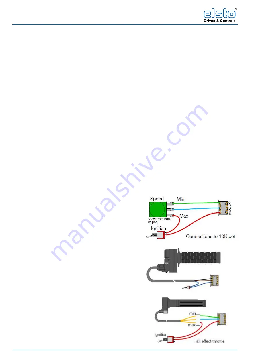
10k Pot
Connects to pins A, C and E.
The ignition switch may be separate or a switched pot can be used.
Other pot values between 5k and 25k can be used, but be aware you
may need to use resistors [either the internal ones or external] to get
an input voltage between 1V & 4V to avoid dead areas at the top and
bottom of the pot travel. The ideal value of the resistors is 1/3 of the
pot value.
Magura Throttle
The Magura throttle, as supplied by Elsto is 5k. Be aware that the
wires on the Magura are slightly oversize for the IDC connector, we
recommend using a short length of 7 x 0.2mm cable as an adaptor to
prevent the pins of the connector shorting out.
Hall Effect Throttle
Connects to pins B, C and D. Pin D has 5v present to feed the pot
top. It should be the type than gives 1v at zero speed and 4v at full
speed. Some throttles are reversed and will not be suitable. Max Hall
current 10mA, for use on 12v and 24v only as standard [Hall throttles
can be used above 24v if a suitable resistor is added in series with
pin D]. There are many makes of Hall effect throttle and wiring colours
are not standardised.
Porter 5-10-10XXX V2.4 07/19
Page 4
www.4qd.co.uk
4. Power Connections
2.5mm² cable is adequate for most applications of the Porter 5, but 4mm
2
or 6mm
2
may be preferred, especially for the motor and for the Porter 10.
Caution
Take care when connecting the battery and motor wiring - connecting a
battery wire to a motor terminal can destroy the controller.
Motor Wiring
If the motor rotates in the wrong direction, exchange M+ and M- wires.
We recommend keeping the motor wires close together, and if possible twisting
them together. If one is not already fitted, we also recommend fitting a 10nF 100V
disc ceramic motor suppression capacitor across the brushes of the motor.
Battery Wiring
Keep the battery wiring as short as possible. The Porter is protected against
reversed battery (60v max) but will not work with the battery reversed. Again, keep
the motor wires close together and twisted together if possible.
Battery Circuit Breaker or Fuse
A circuit breaker or fuse is advised in the battery connections, to act as an
emergency disconnect in the event of a fault in wiring or any other component. In
some applications such a circuit breaker is a legal requirement.
A sensible rating for this breaker is the same as the motor's continuous current.
Otherwise a 30 amp breaker should be adequate for most uses with the Porter 5 or
60 amp with the Porter 10.
5. Throttle Wiring
Connections
Pin
Function
A
1k5 resistor to pin B
B
0v (internally connected to battery
–
ve via reverse polarity protection
MOSFET)
C
Speed voltage from pot (1-4V)
D
5V. This can feed up to 10mA at a battery voltage of 24V or lower.
E
1k5 resistor to pin D
10k Pot
Connects to pins A, C and E.
The ignition switch may be
separate or a switched pot can
be used.
Other pot values between 5k
and 25k can be used, but be
aware you may need to use
resistors [either the internal
Porter 5-10-10XXX V2.4 07/19
Page 5
www.4qd.co.uk
ones or external] to get an input voltage between 1V & 4V to avoid dead areas at
the top and bottom of the pot travel. The ideal value of the resistors is 1/3 of the pot
value.
Magura Throttle
The Magura throttle, as supplied by
4QD is 5k. Be aware that the wires
on the Magura are slightly oversize
for the IDC connector, we
recommend using a short length of
7 x 0.2mm cable as an adaptor to
prevent the pins of the connector
shorting out.
Hall Effect Throttle
Connects to pins B, C and D. Pin D has
5v present to feed the pot top.
It should be the type than gives 1v at
zero speed and 4v at full speed. Some
throttles are reversed and will not be
suitable. Max Hall current 10mA,
for
use on 12v and 24v only
as standard
[Hall throttles can be used above 24v if
a suitable resistor is added in series with
pin D]. There are many makes of Hall
effect throttle and wiring colours are not standardised.
Ignition Switch
An ignition switch should be connected in the pot or throttle circuit to switch off the
controller when not in use. Without this switch the controller is still powered up and
drains about 17mA from the battery.
When ignition is switched off, the controller will ramp the motor down to zero speed
(at whatever deceleration rate you have set) and then switch itself off.
Voltage Input
The Porter may be fed from a voltage
source between 1V and 4V. This can
be PWM supplied from a
microcontroller or even 4QD's own
DMR-203 radio control interface. The
controller will react to the DC average
value of the applied waveform. A 10K
resistor is required to activate the
internal ignition, connected as shown.
More details of how to control the Porter from a microcontroller are in the
knowledgebase on our website.


