Elster Instromet RABO G100 Скачать руководство пользователя страница 5

RABO

®

 Rotary Gas Meter 

05  Elster Instromet

7. Decommissioning and Removal

a)   Always follow your company’s procedures, and local codes 

and ordinances.

b)   Slowly open bypass valve.
c)   Slowly close the meter’s outlet valve, then the inlet valve.
d)   Slowly, completely depressurize the meter piping.


!


WARNING

Failure to depressurize the meter prior to removing meter 

and/or components could result in personal injury and/or 

property damage.

e)   Drain oil from the index end case cover and dispose of the oil 

in accordance with applicable regulations.

f)   If removing the meter from the piping system, loosen flange 

bolts. Ensure meter is properly supported before removing 
bolts completely.

8. Inspection and Maintenance

It is recommended to inspect Elster RABO meters periodically to 
help ensure accurate performance over a long period of time. 
Maintenance intervals can be derived from inspection criteria. 
Routine inspections should include:
a)   Checking to ensure the meter is level in all planes
b)   Listening for abnormal sounds in the meter
c)   Checking oil level and clarity — oil should be red and clear
d)   Checking index movement if gas is flowing
e)   Checking for leaks
f)   Testing the meter’s differential pressure

Routine maintenance should include:
a)   Changing the oil if the color becomes dark
b)   Adding oil if the color is red and clear, but below the 

recommended level

9. Testing

Elster RABO meters should be tested in accordance with applicable 
governing standards. The accuracy of a meter can only be 
determined by comparing results to a traceable reference, typically 
a sonic nozzle, bell, piston or transfer prover. Accuracy may be 
done on site using transfer provers, and typically requires removal 
for testing with other technologies. 
Differential pressure testing is a method of determining whether 
the performance of a rotary meter may have changed over time, 
and can be done on site while the meter is operating under 
pressure. Baseline data must be captured during initial start-up  to 
which future data can be compared.

a) Proving


When testing a meter on a prover, the meter temperature, 
pressure and volume are necessary inputs for the proving 
device. The meter temperature is obtained by a temperature 
probe installed near the inlet of the meter. A thermowell  
can be installed in the meter run piping or on the meter  
itself to facilitate installation of the temperature probe. 


The meter pressure should come from the meter differential  
pressure taps. 

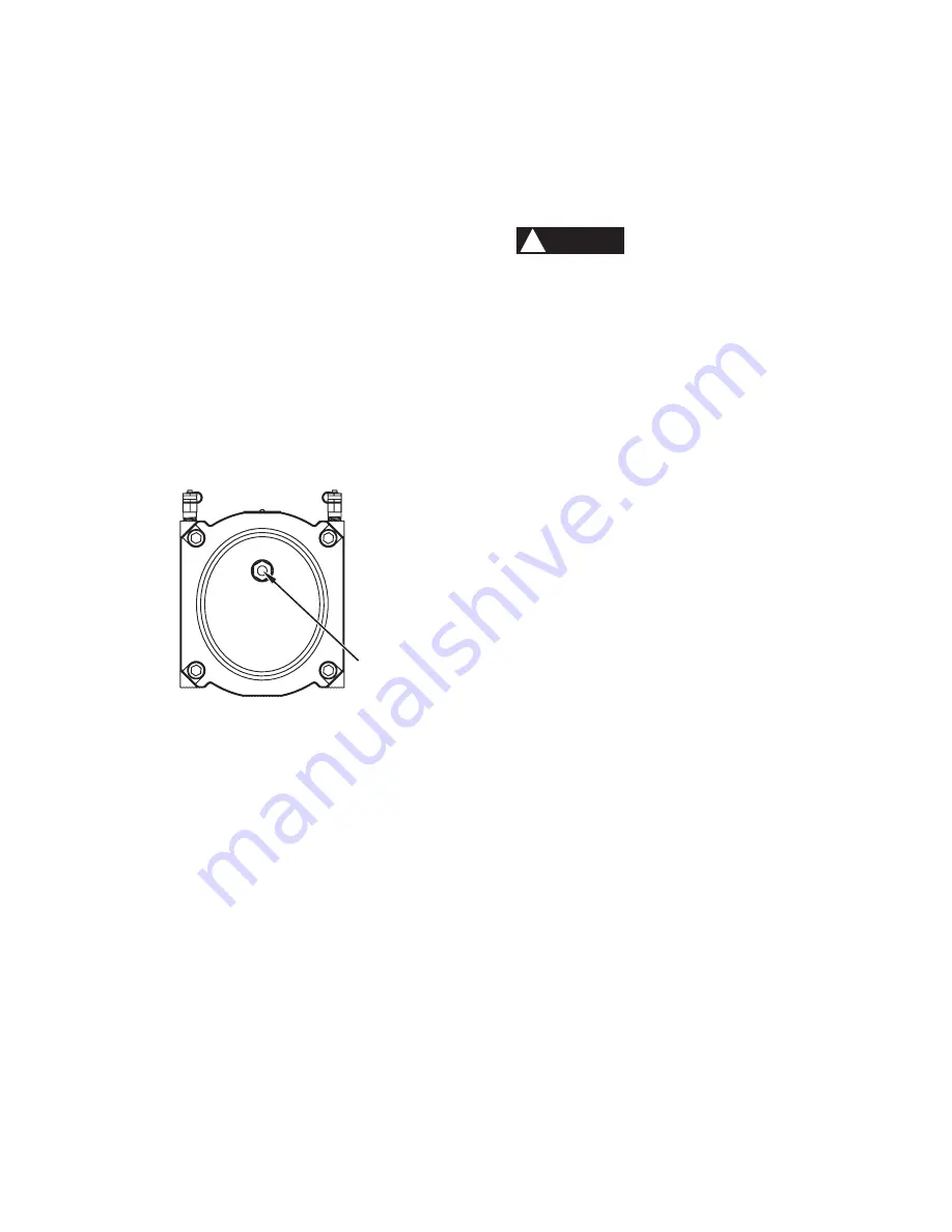
Figure 8. Back of meter

6. Start-up/Commissioning

After the meter has been properly installed, it is important to use 
extreme care during start-up to mitigate adverse conditions that 
can damage the meter. 
a)   Ensure that the maximum operating pressure of the meter 

will not be exceeded.

b)   Always follow your company’s procedures, and local codes 

and ordinances.

c)   With the meter run’s inlet and outlet valves closed, open the 

bypass valve and pressurize the piping system.

d)   With the meter outlet valve closed, slowly open the meter 

inlet valve not to exceed 5 psig per second until pressure 
is equalized throughout the meter piping system. Rapid 
pressurization can cause an over-speed condition and 
can damage the meter. Damage will not be covered 
under warranty. When the meter piping system pressure is 
stabilized, open the inlet valve completely.

e)   Slowly open the meter’s outlet valve until the meter starts to 

operate at low speed. Meter speed can be seen through the 
view port located on the back of the meter [Figure 8]. 

f)   Operate the meter at low flow for 1 to 2 minutes to verify 

proper operation. If the index does not start registration, or 
if you hear knocking or scraping sounds coming from the 
meter, stop the flow and follow appropriate decommissioning 
procedures before removing the meter from the line.

g)   If operation is satisfactory, gradually open the meter’s outlet 

valve to the full open position.

h)   Slowly close the bypass valve.
i)   Check the meter connections for leaks using common 

industry practices.

j)   Clock the meter (see Index section 11c) to confirm the flow rate 

is not exceeding the maximum capacity of the meter.

k)   Perform and record the meter’s differential pressure (see 

Testing section 9b).

VIEW PORT

(DO NOT REMOVE)

Содержание RABO G100

Страница 1: ...Instromet RABO Rotary Gas Meter Instruction Manual ...

Страница 2: ...ng a mechanical index The RABO meter has no wearing parts because precision clearances between the impellers and meter body are maintained by timing gears which are designed to enhance long term accuracy Combining adequate filtration and periodic maintenance a RABO meter will remain accurate over many years As the left impeller rotates toward the vertical position gas enters the cavity created bet...

Страница 3: ...until installation If prolonged storage is experienced RABO meters should be tested for accuracy before installation 5 Installation Elster RABO meters can be installed in horizontal or vertical top inlet piping configurations Vertical top inlet piping is preferred because it enables the meter to pass contaminants more freely through the meter All piping should be properly supported and aligned to ...

Страница 4: ...eter body when tightened 9 Level meter to within 1 16 per foot in all directions and tighten flange bolts evenly maximum 80ft lbs c Adding Oil WARNING Add oil only to the index end of the meter 1 Ensure gas valves are closed and meter and piping are depressurized WARNING Failure to depressurize the meter prior to removing meter and or components could result in personal injury and or property dama...

Страница 5: ...ure data can be compared a Proving When testing a meter on a prover the meter temperature pressure and volume are necessary inputs for the proving device The meter temperature is obtained by a temperature probe installed near the inlet of the meter A thermowell can be installed in the meter run piping or on the meter itself to facilitate installation of the temperature probe The meter pressure sho...

Страница 6: ...f flow if possible Differential pressure tests at flow rates under 25 are hard to interpret because the meter differential pressure at the lower flow rates is quite small The error in measurement is almost as large as the reading itself The meter differential pressure is also a function of line pressure and increases as line pressure increases Testing the meter at the same conditions line pressure...

Страница 7: ...00 940 51 700 1 460 50 3 4 15 300 430 24 000 680 39 300 1 110 61 200 1 730 60 4 1 17 700 500 27 800 790 45 500 1 290 70 700 2 000 75 5 2 21 200 600 33 400 950 54 600 1 550 85 000 2 410 100 6 9 27 200 770 42 700 1 210 69 900 1 980 108 700 3 080 150 10 3 39 100 1 110 61 400 1 740 100 400 2 840 156 300 4 430 175 12 1 45 000 1 270 70 700 2 000 115 700 3 280 180 000 5 100 250 17 2 62 800 1 780 98 700 2...

Страница 8: ...aviolet resistant Lexan cover requires no maintenance and is completely isolated from gas pressure a Rotatable The RABO index can rotate 355 degrees to facilitate desired reading angle depending on the installation orientation To rotate simply grasp the index with both hands and turn to the desired position ANSI Class 125 150 flat face flange connection F D E H G J A B C 2 36 60 2 36 60 M6x1 b How...

Страница 9: ...ndard conditions scfh d Removal Installation and Replacement Steps to replace the RABO meter index 1 Cut the seal wires and remove from the holes Figure 11 2 Remove unscrew the two brass screws on the sides of the index cover Figure 11 5 Remove the three index retaining screws using a Torx T20 driver Figure 13 Figure 13 Index retaining screws INDEX RETAINING SCREW INDEX RETAINING SCREW INDEX RETAI...

Страница 10: ...tection II 2 G EEx ia 2C T4 Figure 16 IN S10 pulser installed Figure 15 Index change gear and locking collar 8 Install the replacement index Orient the index so the mounting holes line up with the posts in the base plate Carefully ensure the shaft on the magnet holder is in the support hole on the index frame Figure 13 Install the three screws to retain the index to the base plate Tighten to snug ...

Страница 11: ... 10mm deep Heavier equipment should be pipe or wall mounted adjacent to the meter Elster provides customized brackets for commonly used equipment Figure 21 Please contact your local Elster representative for details NPT AUXILIARY PORTS Figure 18 Auxiliary ports Figure 20 Vertical installation 13 Thermowell All RABO meters come equipped with two 2 NPT auxiliary ports on the meter body Figure 18 whi...

Страница 12: ...for the most current product information Elster and Elster Logo are trademarks of Elster American Meter Company LLC EAM IM5910 11 14 About Elster Gas Elster provides best in class measurement and regulation products systems and solutions for the safe control and delivery of natural gas across the globe Trusted Brands Elster American Meter Company LLC Elster Perfection Corporation Elster Instromet ...

Отзывы: