Device description
elrest
Automationssysteme GmbH
e
VISIO PTE715_Windows.EN
Page: 31
4.3.4
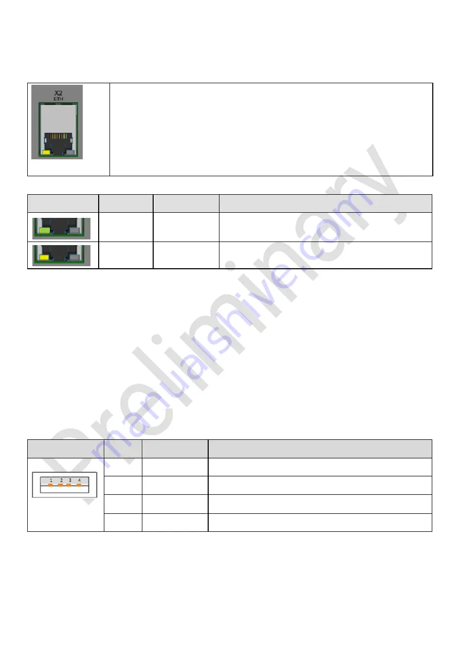
LEDs for the Ethernet interface
Figure 11: LEDs X2
The Ethernet-interface X2 is equipped with twoLEDs for displaying the operating
states LINK and ACTIVITY.
LED
Color
Meaning
LINK
Green
Connection to the communication device is available
ACT
Yellow
Communication is available
Figure 12: LEDs X2 color
4.3.5
X4 USB0 2.0 Host interface
The interfaces is executed as a USB 2.0-Host interface with Type A socket.
Power supply can be max. 500 mA for each interface and is protected by overcurrent detection
The connection for this interface acc. the USB-specification, 2.0 High-Speed,
max. transmission rate: 480 MBit/s.
The cable length must be <3 m
The follwing table and illustration shows the pin assignment of this interface.
Interface X4
PIN
Allocation
Function
Figure 13: X4 USB- interface
1
USB_VCC1
USB + 5 VDC
2
USB_N
USB Data line D-
3
USB_P
USB Data line D+
4
USB_GND
USB GND
4.3.6
S2 key
„
SLEEP
/ RESET“
The key S2 operates as follows:
Press
>
8 sec:
Triggering RESET on the CPU with Warm-Boot function;


