background image

This Information Technology Equipment (ITE) is required to have a CE Mark on the manufacturer’s

label which means that the equipment has been tested to the following Directives and Standards:

This equipment has been tested to the requirements for the CE Mark as required by EMC

Directive 89/336/EEC indicated in European Standard EN 55022 Class B and the Low Voltage

Directive 73/23/EEC as indicated in European Standard EN 60950.

D) General Information to all Users: This equipment generates, uses and can radiate radio

frequency energy. If not installed and used according to this manual the equipment may cause

interference with radio and television communications. There is, however, no guarantee that

interference will not occur in any particular installation due to site-specific factors.

1) In order to meet emission and immunity requirements, the user must observe the following:

a) Use only the provided I/O cables to connect this digital device with any computer.

b) To ensure compliance, use only the provided manufacturer’s approved line cord.

c) The user is cautioned that changes or modifications to the equipment not expressly

approved by the party responsible for compliance could void the user’s authority to operate

the equipment.

2) If this equipment appears to cause interference with radio or television reception, or any other

device:

a) Verify as an emission source by turning the equipment off and on.

b) If you determine that this equipment is causing the interference, try to correct the

interference by using one or more of the following measures:

i) Move the digital device away from the affected receiver.

ii) Reposition (turn) the digital device with respect to the affected receiver.

iii) Reorient the affected receiver’s antenna.

iv) Plug the digital device into a different AC outlet so the digital device and the

receiver are on different branch circuits.

v) Disconnect and remove any I/O cables that the digital device does not use.

(Unterminated I/O cables are a potential source of high RF emission levels.)

vi) Plug the digital device into only a grounded outlet receptacle. Do not use AC

adapter plugs. (Removing or cutting the line cord ground may increase RF emission

levels and may also present a lethal shock hazard to the user.)

If you need additional help, consult your dealer, manufacturer, or an experienced radio or television

technician.

34   User Guide

Содержание ET1515L Series

Страница 1: ...Touchmonitor User Guide 1515L 15 LCD Desktop Touchmonitor 1000 Series Revision B...

Страница 2: ...User Guide 15 LCD Desktop ET1515L Series Revision B P N 008612...

Страница 3: ...ystems makes no representations or warranties with respect to the contents hereof and specifically disclaims any implied warranties of merchantability or fitness for a particular purpose Elo TouchSyst...

Страница 4: ...erial Touch Driver for MS DOS and Windows 3 1 14 Installing the USB Touch Driver 15 Installing the USB Touch Driver for Windows XP Windows 2000 Me 95 98 and NT 4 0 15 Chapter 3 Operation 17 About Touc...

Страница 5: ...sistor TFT liquid crystal display to provide superior display performance Amaximum resolution of XGA 1024x768 is ideal for displaying graphics and images Other outstanding designs that enhance this LC...

Страница 6: ...rcuitry allows the monitor to function at the precision of a fixed frequency High contrast color TFT LCDdisplay support resolution up to XGA1024x768 Compatible with VGA SVGA XGA non interlaced and mos...

Страница 7: ...your LCDtouchmonitor and how to install the driver software Unpacking Your Touchmonitor Check that the following 8 items are present and in good condition LCD monitor VGAcable USB cable Serial cable E...

Страница 8: ...touch screen USB cable but not both to the rear side of the computer and the other end to the LCD monitor Tighten by turning the two thumb screws clockwise to ensure proper grounding optional module U...

Страница 9: ...Product Overview Main Unit Rear View 2 11...

Страница 10: ...chSystems web site at www elotouch com Your Elo touchmonitor is plug and play compliant Information on the video capabilities of your touchmonitor is sent to your video display adapter when Windows st...

Страница 11: ...tically detects the CDand starts the setup program 3 Follow the directions on the screen to complete the driver setup for your version of Windows 4 If theAutoStart feature is not active 5 Click Start...

Страница 12: ...o asks you for the paths to use during installation or you may use its defaults INSTALL creates directories as necessary and warns you if they exist If you are updating your software you may wish to s...

Страница 13: ...se Finish If Windows 98 Windows Me or Windows 2000 does not start theAdd New Hardware Wizard NOTE For Windows 2000 you must have administrator access rights to install the driver 1 Insert the Elo CD R...

Страница 14: ...2 16 User Guide...

Страница 15: ...n that is 1024x768 at 60k 75 Hz Use the Display control panel in Windows to choose 1024x768 resolution Operating in other resolutions will degrade video performance For further information please refe...

Страница 16: ...crease value of the adjustment item 3 Select item 3 1 Enter brightness adjustment 2 Decrease value of the adjustment item 3 Select item counter clockwise 4 Select Selects the adjustment items from the...

Страница 17: ...or counterclockwise through the menu Press the Enter key the parameter will be highlighted when selected 3 To quit the OSD screen at any time during the operation press the Menu key If no keys are pr...

Страница 18: ...side OSD V Position Moves the OSD position vertically on the screen When the button is pressed the OSD control menu will move to the top side of the screen Likewise when the button is pressed the OSD...

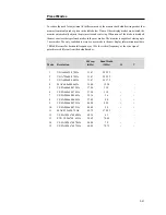
Страница 19: ...on must have 1 KHz difference for horizontal frequency or 1 Hz for vertical frequency or the sync signal polarities are different from the default modes H Freq Band Width Mode Resolution KHz MHz H V 1...

Страница 20: ...n use for a long time NOTE The monitor automatically goes through the Power Management System PMS steps when it is idle To release the monitor from PMS condition press any key on the keyboard or move...

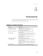
Страница 21: ...or Adjustments section to adjust the brightness The screen is blank During operation the monitor screen may automatically turn off as a result of the Power Saving feature Press any key to see if the s...

Страница 22: ...4 24 User Guide...

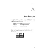
Страница 23: ...tion You can lower the resolution setting of a monitor but not increase it InputVideo 15 LCD 640x480 VGA Transforms input format to 1024x768 800x600 SVGA Transforms input format to 1024x768 1024x768 X...

Страница 24: ...e the pixel in column 45 and row 26 of the input video is in column 45 and row 26 of the LCD For the case when the input video is at a lower resolution than the native resolution of the LCD the direct...

Страница 25: ...h a 3 wire grounding power cord The power cord plug will only fit into a grounded outlet Do not attempt to fit the plug into an outlet that has not been configured for this purpose Do not use a damage...

Страница 26: ...any strong dissolvent Do not use thinner or benzene abrasive cleaners or compressed air To clean the display unit cabinet use a cloth lightly dampened with a mild detergent Avoid getting liquids insi...

Страница 27: ...APPENDIX C TECHNICAL SPECIFICATIONS C 29...

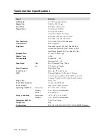
Страница 28: ...Vertical 60 o 40 o Horizontal 60 o 60 o Input Signal Video R G B Analog 0 7Vp p 75 ohm Sync TTL Positive orNegative Signal Connector MiniD Sub 15 pin Front Control Menu Select Power OSD Contrast Brigh...

Страница 29: ...Surface Durability Meets TaberAbrasion Test ASTM D1044 CS 10F wheel 500 g Meets pencil hardness 3H Expected Life AccuTouch technology has been operationally tested to greater than 35 million Performan...

Страница 30: ...15 LCD Touchmonitor ET1515L XXXA 1 Dimensions C 32 User Guide...

Страница 31: ...ion or misuse can provide a shock hazard that can result in serious injury or death 3 Contact a qualified electrician or the manufacturer if there are questions about the installation prior to connect...

Страница 32: ...difications to the equipment not expressly approved by the party responsible for compliance could void the user s authority to operate the equipment 2 If this equipment appears to cause interference w...

Страница 33: ......

Страница 34: ......

Страница 35: ...package the allegedly defective Product in its original shipping carton s or a functional equivalent and shall ship to Seller at Buyer s expense and risk Within a reasonable time after receipt of the...

Страница 36: ...es the risk and agrees to indemnify Seller against and hold Seller harmless from all liability relating to i assessing the suitability for Buyer s intended use of the Products and of any system design...

Страница 37: ...rolling 23 Input Signal 30 Installation and Setup 9 Installing the Driver Software 12 Installing the Serial Touch Driver 13 Installing the Serial Touch Driver for MS DOS and Windows 3 1 14 Installing...

Страница 38: ...h Activation Force AccuTouch 31 Touch Interface Connection 11 Touch not working 23 Touch Panel optional 30 Touchmonitor Safety 27 Touchmonitor Specifications 30 Touchpoint Density AccuTouch 31 Trouble...

Страница 39: ......

Страница 40: ...ems Inc Elo TouchSystems GmbH Co KG Elo TouchSystems Touch Panel Systems K K 301 Constitution Drive Haidgraben 6 Diestsesteenweg 692 Sun Homada Bldg 2F Menlo Park CA 94025 D 85521 Ottobrunn B 3010 Kes...

Отзывы: