background image

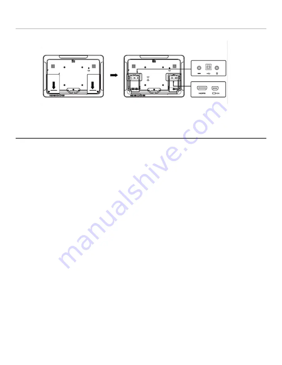
Connector Panel & Interfaces 


Touchmonitor Connections 


1. Connect the HDMI or Mini-VGA video cables between the m 


2. \onitor

’s HDMI/Mini-VGA input connectors and your HDMI/VGA video source, respectively. 


Tighten the video cable

’s screws for best performance. 


2. Connect the USB touch cable between the monitor

’s USB connector and your PC’s 

USB port. 


3. Connect the audio cable between the monitor

’s Audio In jack and your audio source. 


4. Select the correct power clip for your region and clip to the power adapter. Connect the 
power adaptor

’s input connector to the power source. Connect the power adaptor’s DC output 

connector to the monitor

’s input power jack. 


5. The touchmonitor ships in an OFF state. Press the power button to turn it on. 


User Manual: 1002L, 1502L, 2002L 


UM600012 

Rev D,

 Page 7 of 24 

Содержание ET1002L

Страница 1: ...USER MANUAL Elo Touch Solutions ET1002L ET1502L and ET2002L Touchmonitors UM600012 Rev D...

Страница 2: ...Stand is not included with 1002L monitor User Manuals CD Japanese language regulatory information pamphlet Quick Install Guide Mini VGA to VGA cable HDMI cable USB cable Audio cable Power adaptor with...

Страница 3: ...002L monitor does not ship with a stand Low profile hostess position To convert the stand into the high profile upright position secure the thumbscrews into the high or H screw holes in the bottom of...

Страница 4: ...monitor s USB connector and your PC s USB port 3 Connect the audio cable between the monitor s Audio In jack and your audio source 4 Select the correct power clip for your region and clip to the powe...

Страница 5: ...nloads Driver DriverDownload Default aspx 2 Select the operating system from Operating System dropdown menu 3 Select the technology from Technologies dropdown menu 4 Click on the driver version requir...

Страница 6: ...and VESA MIS B 100 C For the 1502L and 2002L touchmonitors a four hole 75x75mm and 100x100mm mounting pattern for M4 screws is provided on the rear of the monitor Remove the stand using a Phillips sc...

Страница 7: ...g pattern for M4 screws is provided on the bottom of stand base for mounting or securing For the 2002L touchmonitor threaded through holes are provided on the bottom of the stand base for mounting or...

Страница 8: ......

Отзывы: