


ELNEC s.r.o.
Specification of ISP connector pins depends on the device which you want to work with.
rogrammer (Pg4uw), menu
Device / Device Info
g (ISP) option of respective device must be
selected. It is indicated by (ISP) suffix after the name of selected device.
These specifications correspond with application notes published by device
manufacturers. Application notes can be found on
www.elnec.com
You can find it in the control SW for p
(Ctrl+F1)
. Note the ISP programmin
,
section
Support /
Application Notes
.
Note:
Pin no. 1 is signed by t
necto s
.
riangle mark on ISP cable con
r
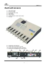
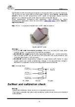
BeeHive8S ISP cable
Warnings:
•
Use only
ISP cable from delivery package
. When you use other ISP cable (other
material, length…), programming may become unreliable.
•
BeeHive8S
can
supply
power to the programmed device (pin 1 of ISP connector)
and the target system (pin 19 and 20 of ISP connector) with some limitations (see
Technical specification / ISP connector).
•
BeeHive8S
applies programming voltage to target device and checks its value
(target system can modify programming voltage). If the programming voltage is
different from expected, no action with target device will be executed.
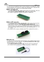
d driver
Note:
H/L/rea
R1
H/L driver
in programmer
pin of ISP
connector
read driver
in programmer
R2
PU/PD driver
in programmer
R3
R1=180R R2=1k3 R3=22k
Selftest and calibration check
Warning:
Selftest and calibration check can be run in engineering mode only.
This mode is available only when external display, keyboard and mouse are connected
to BeeHive8S.
9