background image

20

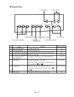
Operation panel

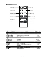
Wireless remote control

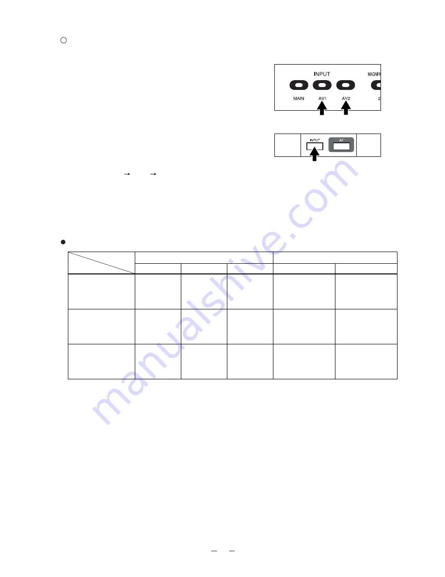
Input selection

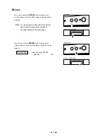
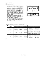
The respective images from two different AV sources such

as a VCR and a video camera can be alternately presented

on a monitor by selecting the AV source by pressing the

desired input selection buttons without changing cable

connections.  The input can be switched by pressing the

input select button 

[AV1]

or 

[AV2]

on the operation panel

or the input select button 

[INPUT]

on the wireless remote

control. The lighting of the indicator lamp indicates which

input is now selected.

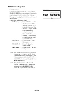
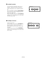
Every time the input selection button 

[INPUT]

on the

wireless remote control is pressed, input is switched in a

cycle of 

the 

Main AV1 AV2

.

Input selection is possible as shown in the table on the next

page.  Signal change, such as "from C-video input to S-

video output" is not available.

Table of Video- and Audio-in/out Terminal Selections

Main camera

S-video signal

INTERNAL

AV1

AV2

Input

Output signal

Video-out terminal

Audio-out terminal

RCA terminal

BNC

R

 terminal

L

 terminal

S-VIDEO terminal

Main camera

C-video signal

Main camera

C-video signal

Main body input

microphone audio

(monaural)

Main body input

microphone audio

(monaural)

AV1 input

S-video signal

AV1 input

C-video signal

AV1 input

C-video signal

AV1 input external audio
signal L channel (stereo)

+

Main body input microphone

audio (monaural)

AV1 input external audio

signal R channel (stereo)

+

Main body input microphone

audio (monaural)

AV2 input

S-video signal

AV2 input

C-video signal

AV2 input

C-video signal

AV2 input external audio
signal L channel (stereo)

+

Main body input microphone

audio (monaural)

AV2 input external audio

signal R channel (stereo)

+

Main body input microphone

audio (monaural)

Содержание EV-4400AF

Страница 1: ...VISUAL PRESENTER INSTRUCTION MANUAL Please read this instruction manual carefully before using this Visual Presenter and keep it for future reference...

Страница 2: ...ended to operate from battery power or other sources refer to the operating instructions Grounding or Polarization This product may be equipped with either a polarized 2 wire AC line plug a plug havin...

Страница 3: ...TIC ENVIRONMENT THIS PRODUCT MAY CAUSE RADIO INTERFERENCE IN WHICH CASE THE USER MAY BE REQUIRED TO TAKE ADEQUATE MEASURES INFORMATION This equipment has been tested and found to comply with the limit...

Страница 4: ...C 40 C 41 F 104 F Humidity 30 85 No condensation Use a soft dry cloth for cleaning Do not use any volatile solvent such as thinner or benzine Do not directly point the camera lens into the sun or the...

Страница 5: ...Simple steps for presenting printed material 16 Simple steps for showing transparent material such as overhead transparencies or slide film 17 Convenient use of the camera 17 7 VARIOUS FUNCTIONS 18 L...

Страница 6: ...eset No and move No MEMORY 32 9 RS 232C SPECIFICATIONS 33 Setting up 33 Cable connection 34 RS 232C connector specifications DSUB 9P 34 Table of the communication commands 35 Data format specification...

Страница 7: ...acket Socket Attach this holder for normal use Swing away this holder for viewing a far away object 7 Lighting Unit Arm 6 Lighting Unit 10 Carryng Handle 14 Mic Jack MIC 9 Operation Panel 16 Scroll Mo...

Страница 8: ...s To turn ON OFF the lighting P 17 P 18 18 Zoom Buttons To change the image size P 16 P 19 P 24 19 Auto Focus Button To focus automatically One shot auto focus P 16 P 24 FOCUSFREE Front Panel 18 Zoom...

Страница 9: ...n Button To present black and white material such as documents P 22 23 Posi Nega Conversion Button To show negative films P 17 P 22 24 White Balance Button To change the mode between AUTO and ONE PUSH...

Страница 10: ...al when input selection is set at AV1 36 Audio in Terminal2 Audio signal from this terminal is output through the INPUT AV2 AUDIO audio out terminal when input selection is set at AV2 37 Video out Ter...

Страница 11: ...TELE To zoom in P 16 P 19 P 24 46 ZOOM WIDE To zoom out P 16 P 19 47 INPUT To change the input system P 20 48 LAMP To turn ON OFF the lamp P 17 P 18 49 MOVE To call the operating status of the Presen...

Страница 12: ...m 23 ft or less from the light receiving area to the front of the wireless remote control Angle Approx 30 degrees or less from the light receiving area to the front of the wireless remote control righ...

Страница 13: ...ment P 21 Mouse pointer P 26 Mouse functions in the OSD Menu screen display P 28 Remote setting P 32 Note When using the mouse connect the mouse before turning ON the power supply to the Presenter If...

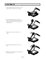
Страница 14: ...tton and raise the column until the column lock release button returns to the original position Make sure that the column has been completely locked 3 Turn the main camera head as illustrated until it...

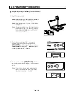
Страница 15: ...o the S video in terminal Connect the S video out terminal mini DIN 4P of the Presenter to the S video in terminal of the TV video monitor For the S video mode use an S video connection cable availabl...

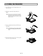
Страница 16: ...ht storage position of the column Never apply excessive force to the column 2 Turn the main camera head as illustrated until it is stopped Note Be sure to set the camera head in the illustrated positi...

Страница 17: ...the object on the stage Adjust the image size according to the object size using the zoom buttons TELE WIDE on the front panel or the zoom buttons TELE WIDE on the wireless remote control while watch...

Страница 18: ...base button BASE on the front panel or the lamp button LAMP on the wireless remote control again Front panel Wireless remote control Simple steps for showing transparent material such as overhead tra...

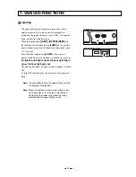
Страница 19: ...e the lamp button LAMP on the wireless remote control is pressed lighting is switched in a cycle of the lighting unit lights up the base light lights up the base light goes out The lighting unit light...

Страница 20: ...is lower within the electronic zoom range For some material objects horizontal stripes may be conspicuous Press the zoom button WIDE on the front panel or wireless remote control and the image will g...

Страница 21: ...nal change such as from C video input to S video output is not available Table of Video and Audio in out Terminal Selections Main camera S video signal INTERNAL AV1 AV2 Input Output signal Video out t...

Страница 22: ...When the OSD Main menu is in display the OSD screen is not in display but the mouse pointer is in display Center button To turn ON OFF the OSD Menu screen Mouse wheel To scroll up down the enlarged s...

Страница 23: ...mode When the color B W selection button COLOR B W is pressed again the indicator lamp goes out and the normal COLOR mode is resumed Operation panel Posi Nega conversion To show a negative film Press...

Страница 24: ...To set the push set white balance By pressing the button WHITE BALANCE the white balance for the then color temperature is fixed Note The automatically followed color temperature ranges from approx 30...

Страница 25: ...or wireless remote control and press the auto focus botton However the objects listed below may not be brought into focus in the auto focus mode In these cases use the manual focus mode Objects bearin...

Страница 26: ...ly read upon turning ON the power supply for startup The operation status that can be saved includes Present zoom angle of view Adjustment status of AUTO iris level White balance mode Lighting status...

Страница 27: ...nt to save Close the status or the OSD and then press the preset button PRESET and the present operating status will be saved in the selected No 1 has been selected on default Presetting by automatica...

Страница 28: ...or bracket socket Note When connecting to the LCD monitor out terminal confirm the right connection direction Note When using the LCD monitor connection cable do not use the AC adapter or video cable...

Страница 29: ...MENU on the front panel or the center button of the mouse is pressed the OSD Setting Main menu MAIN MENU is displayed Choose the item of each function in the main menu How to adjust the OSD on the ope...

Страница 30: ...128 to 127 128 to 127 128 to 127 128 to 127 CHROMA MODE R GAIN B GAIN R PHASE G PHASE B PHASE Ye PHASE MANUAL 0 0 0 0 0 0 Monitor screen Electronic shutter SHUTTER Menu sequence MAIN MENU SHUTTER To...

Страница 31: ...42 OFF Monitor screen AGC Auto gain control Menu sequence MAIN MENU OPTION AGC To set the auto gain control When the object is dark The AGC can gain up the image of the object to be lighter Initial se...

Страница 32: ...changed Initial setting ON Electronic zoom ON OFF selection Menu sequence MAIN MENU OPTION E ZOOM OPTION AGC DETAIL POINTER E ZOOM REMOTE OFF 0 WHITE ON MOUSE Monitor screen Select which equipment th...

Страница 33: ...ce MAIN MENU MEMORY MOVE NUM Select the No from which you want to call the operation status of the Presenter in MOVE Reference Page About the preset and move operation P 25 Selection of preset No and...

Страница 34: ...RS 232C cable available in the market make sure of the connection shown the next page Note To protect the Presenter and the PC be sure to turn OFF all the power switches of all equipment before conne...

Страница 35: ...ion of data Visual Presenter PC CD RXD TXD DTR SG DSR RTS CTS Carrier Detect Received Data Transmitted Data Data Terminal Ready Signal Ground Data Set Ready Request To Send Clear To Send Comments Cabl...

Страница 36: ...lect the Lighting Input selection Command to select the Input Posi Nega conversion Command to convert Posi Nega Color B W selection Command to select Color B W Mouse Pointer display Command to turn ON...

Страница 37: ...itches on the front panel operation panel and wireless remote control Default Command to reset to the initialized mode Status request Command to inquire the status of the equipment ROM version Command...

Страница 38: ...a set of 7 bytes as follows S T X E T X Command PC Visual Presenter ACK Data Parameter 02H 03H 06H Data format specifications This command is executed in the form of 1 command 1 packet The next comma...

Страница 39: ...dgement is transmitted Connect the RS 232C cable correctly and fix it firmly with the connector set screws before the operation Transmission specifications Full duplex start stop sync mode Start bit 1...

Страница 40: ...ed ON after preheating for 2 seconds This is not a fault Image is too dark The intensity of illumination is not sufficient Press the upper button UPPER on the front panel or the lamp button LAMP on th...

Страница 41: ...ck 75 unbalanced BNC connector 75 unbalanced S video output Mini DIN 4P connector 75 unbalanced Audio output stereo RCA pinjack applicable impedance 10k or more 10dB Input terminal S video input Mini...

Страница 42: ...xternal sync automatic selection Resolution More than 470 TV lines Y signal with horizontal More than 350 TV lines Vertical S N ratio 48 dB with adjusting the detail min Output signal C video S video...

Страница 43: ...gements ELMO FOCUSFREE are trademarks of ELMO CO Ltd Item Specifications Upper High frequency lighting mode 3 wave length type fluorescent lamp 6W Model FHL6EX N Base High frequency lighting mode 3 wa...

Страница 44: ...LMO Mfg Corp 1478 Old Country Road Plainview NY 11803 5034 Tel 516 501 1400 Fax 516 501 0429 E mail elmo elmousa com web http www elmousa com Canada ELMO Canada Mfg Corp 44 West Drive Brampton Ontario...

Отзывы: