background image


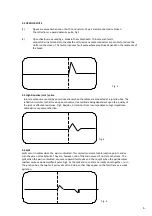
5.2 OPEN CIRCUITS 

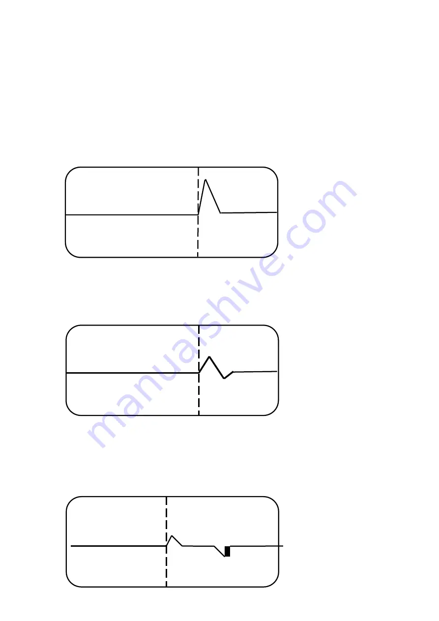
(1)            Opens are caused when one or both. Conductors of a pair are disconnected or broken.  


The reflection is  upward polarity  pulse, Fig.2 

 
(2) 

Open sheaths are caused by a  break in the cable sheath. To locate such faults, 
connect the line terminals to the sheath and to as many cable conductors as possible to reduce the 
clutter on the screen. This fault produces a fault pulse whose amplitude depends on the resistance of 
the break


        Fig. 2 


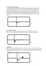
5.3 High Resistive joint / splice 

Joints or splices are caused by poor connections when the cables are connected at a junction box. The 
reflection is similar to that for an open conductor, its amplitude being dependent upon the  quality of 
the joint or effective resistance. Fig 3. Besides, A transition from low impedance to high impedance 
cable also cause same reflection. 


Fig. 3 


5.4 Split


Splits occur in cables when the  pair is untwisted. This normally occurs at cable junction points, and as 
such they are not really faults. They are, however, one of the main causes of clutter on the trace. The 
split, when the pair is untwisted, causes an upward fault pulse and the re-split, when the pair becomes 
twisted, causes a downward fault pulse Fig 4. As the split and re-split are normally close together, i.e. in 
the junction box, the two fault pulses almost coincide, so that they appear on the fault trace as a weak 
agitation. 


Fig. 4


6. 


Содержание TDR-44

Страница 1: ...CABLE FAULT LOCATOR Handheld Graphical TDR Model TDR 44 Operation Manual ...

Страница 2: ...Contents page 1 Introduction 1 2 Batteries 1 3 Safety Rules 2 4 Operating Instructions 2 5 Type of cable fault 5 6 Specification 8 7 Accessories 9 8 Repair and servicing 9 9 Warranty 9 ...

Страница 3: ...d upon the dielectric insulation of the cable and the Fault Locator can be set to suit any type of cable dielectric A list of typical propagation velocity factor values is given in table A and a type of cable fault can be determined as section 5 of this manual The Fault Locator is available with 120 ohm output impedance and 0 67 defaults PVF 2 Batteries The unit operate from 6 AA size batteries In...

Страница 4: ... with LED back lighting A visual representation of the reflected pulse is provided on a single trace The break point can be aligned with the cursor by using the arrow keys when in locate mode and the distance to fault is displayed in meters or feet The instrument powers up in the locate mode with 3000 meters range selected and the propagation velocity factor set at the optimum for each cable fault...

Страница 5: ... rate than normal in the direction indicated Up key The Up key increases the Propagation Velocity Factor scrolls the Cursor right scrolls up through the Ranges and toggles measure unit between Metres and Feet with the appropriate mode selected When the Locate Mode is selected and the key pressed twice and then held the cursor scrolls at a faster rate than normal in the direction indicated 4 1 FAUL...

Страница 6: ...ocity factor by means of the arrow keys when in PVF Mode Listed in Table A are typical values of propagation velocity factor for various cable dielectrics Use the menu select key to select metres or feet for the cursor value 5 Inspect the trace for a fault pulse and reduce to the minimum Range where the fault pulse is clearly visible 6 Change to locate mode and operate the cursor keys to position ...

Страница 7: ... are suitable for locating a variety of faults and cable conditions A selection of these is outlined below 5 1 SHORT CIRCUITS 1 Shorts between two conductors of a cable pair The reflection has the downward Polarity pulse Fig 1 2 Sheath shorts are caused when a conductor in a cable makes contact with the metallic sheath of the cable To locate a sheath short first disconnecting the sheath from earth...

Страница 8: ...reflection is similar to that for an open conductor its amplitude being dependent upon the quality of the joint or effective resistance Fig 3 Besides A transition from low impedance to high impedance cable also cause same reflection Fig 3 5 4 Split Splits occur in cables when the pair is untwisted This normally occurs at cable junction points and as such they are not really faults They are however...

Страница 9: ...ay produce only very small fault pulses due to the restricted volume of water Besides a transition from low impedance to high impedance cable also cause same reflection Fig 5 5 6 Low Water at Cable joint This fault is similar to item 5 5 but happen at Cable joint which contaminated by wet environment Fault trace is as Fig 6 which after splice be followed by small sine or square that decreasing gra...

Страница 10: ...nge Gain Auto Set across screen Output Pulse 5V nominal in open circuit PVF Variable from 0 01 to 0 99 Output impedance 120 Ohm Pulse Width Automatically varied Connectors Two 4mm safety terminals LCD Display 128x64 graphic LCD with backlight Update Rate Once per second No touch shutdown 5 minutes Display view area 44x62 mm Power supply Batteries 6 AA alkaline or nickel cadmium cells Battery Low i...

Страница 11: ...l 8 Repair and servicing This instrument is not a user serviceable item other than the replacement of batteries In the unlikely event of failure please return to the nearest distributor or Manufacturer Manufacturer address Pantong Technologies Co Ltd 99 213 Moo 10 Bangkrang Muangnonthaburi Nonthaburi 11000 THAILAND 9 ...

Отзывы: