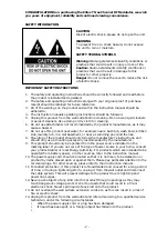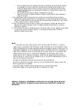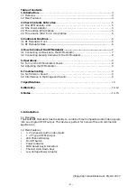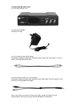
- 6 -
3. Controls & Functions
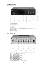
3.1 RF Modulator Front
1.
Power Indicator
2.
Power Switch
3.
LED Channel Display
4.
Input A
5.
Input B
6.
Input C
7.
MOD Select Key – Used to Select Modulator A, B or C for Setup
8.
Channel Up
9.
Channel Down
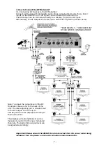
3.2 RF Modulator Back
10.
RF Output – Connect to UHF Input of TV Set or Cable Converter
11.
Gain Adj. – RF Output Level Control
12.
C - Video Device Input
13.
C – L&R Audio Device Input
14.
B - Video Device Input
15.
B – L&R Audio Device Input
16.
A - Video Device Input
17.
A – L&R Audio Device Input
18.
Power Adaptor Input (9 VDC @ 300 mA)


