


Single Alarm Output Method: One alarm output
with a steady / pulse option.
8
Ohm
8
Ohm
2 Speakers in Series
Total resistance = 16 Ohms
8
Ohm
8
Ohm
3 Speakers - 2 Series, 1 Parallel
Total resistance = 6 Ohms
8
Ohm
8
Ohm
8
Ohm
Note: This speaker
will be louder than
the other two.
Low Current Trigger Method: One or two
positive alarm outputs capable of 30 mA ea.
The operational current will be supplied from a
co12 Vdc auxiliary source. The siren and
voice channel trigger terminals draw only 30 mA
from the control alarm outputs.
A steady 9 to 14 Vdc on Channel 3 (
+S3
) will
activate the Siren sound and optionally the Voice
Channel 1 (
+V1
). A pulsing voltage (.5 to 2 pulses
per second) on Channel 3 (+S3) will activate the
Temporal Coded Bell sound and and optionally the
Voice Channel 2 (
+V2
).
Note:
Pulsing is only detected on teS3
and terminal -VS.
Industrial Buzzer Siren Sound
The industrial buzzer siren sound is triggered by
connecting Channel 3 (
+S3
) and Channel 4 (
+B4
)
together. It may be triggered along with Voice
Channels 1 and/or Voice Channel 2 as described
previously.
+12 Volts DC
Negative
+V1, Voice Channel 1
+V2, Voice Channel 2
+S3, Siren Channel 3
+B4, Bell Channel 4
-VS, Voice/Siren Ch 1 & 3
Speaker
Speaker
}
4 Ohm Max. Load
8 Ohm
Speakers
Negative
ELK-120
For Low Current Trigger
+12 Volts DC
+12 Volts DC
Industrial Buzzer
Siren
Connect Ch 3 & 4
+12 Volts DC
Negative
+V1, Voice Channel 1
+V2, Voice Channel 2
+S3, Siren Channel 3
+B4, Bell Channel 4
-VS, Voice/Siren Ch 1 & 3
Speaker
Speaker
}
4 Ohm Max. Load
8 Ohm
Speakers
Ch 1 & 3
Ch 2 & 4
Negative
ELK-120
Control
BURG.
Output
FIRE
Output
Low Current,
Positive Outputs
+12VDC Power
+12 Volts DC
Negative
+V1, Voice Channel 1
+V2, Voice Channel 2
+S3, Siren Channel 3
+B4, Bell Channel 4
-VS, Voice/Siren Ch 1 & 3
Speaker
Speaker
}
4 Ohm Max. Load
8 Ohm
Speakers
+12VDC Ch 1 & 3
Negative
+12VDC Power
Steady = Ch 1 & 3
Pulsing = Ch 2 & 4
Ch 3 Must Be
Connected For
Pulsing Input
ELK-120
Pulse / Steady
Positive Output
Control
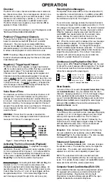
2 Speakers in Parallel
Total resistance = 4 Ohms
Always add a 1.5 Amp fuse in series
with outdoor speaker. Shorting of the
outdoor speaker wires will blow this fuse
but other speaker(s) will still work.
INSTALLATION & HOOKUP EXAMPLES
Standard Method: Control panel with two
alarm outputs capable of 2 Amps max. each.
Single Alarm Output With Switched Negative:
Controls panels such as DSC provide an alarm
output with a switched negative, requiring a
special hookup.
The
-VS
terminal internally activates Voice
Channel 1 and Siren Channel 3 upon a steady
voltage input. A pulsing voltage input (.5 to 2
pulses per second) on terminal -VS internally
activates Voice Channel 2 and Bell Channel 4.
+12 Volts DC
Negative
+V1, Voice Channel 1
+V2, Voice Channel 2
+S3, Siren Channel 3
+B4, Bell Channel 4
-VS, Voice/Siren Ch 1 & 3
Speaker
Speaker
}
4 Ohm Max. Load
8 Ohm
Speakers
DSC
Security
Control
Negative
Switched
Alarm,
Pulsing
Fire
Negative
+12VDC Alarm
Output
ELK-120
Negative
Alarm
Output
Note: Dashed Lines Indicate Optional Connections.
All current must be supplied from the Burg and
Fire Outputs on the Control. Average current
draw with 8 Ohm speaker load is 1.2 Amps, or 1.8
Amps with 4 Ohm load.
+12 Volts DC
Negative
+V1, Voice Channel 1
+V2, Voice Channel 2
+S3, Siren Channel 3
+B4, Bell Channel 4
-VS, Voice/Siren Ch 1 & 3
Speaker
Speaker
}
4 Ohm Max. Load
8 Ohm
Speakers
Ch 1 & 3
Ch 2 & 4
Negative
ELK-120
Control
BURG.
Output
FIRE
Output
High Current,
Positive Outputs


