background image

K7S5A2 V1.0 

27 

PWRFAN2

P

W

R

FA

N

1

SDR1

DDR1

DDR2

SDR2

LED1

IDE2

J2

C

D

1

AGP1

PCI1

PCI2

PCI3

PCI4

PCI5

CNR1

BT1

USB2

U

S

B

3

JP1

WOL1 WOM1

S

P

K

R

1

PA

N

E

L

1

IR

1

FDD1

JP4

JP3

C

D

2

IDE1

1

1

1

1

1

1

1

1

1

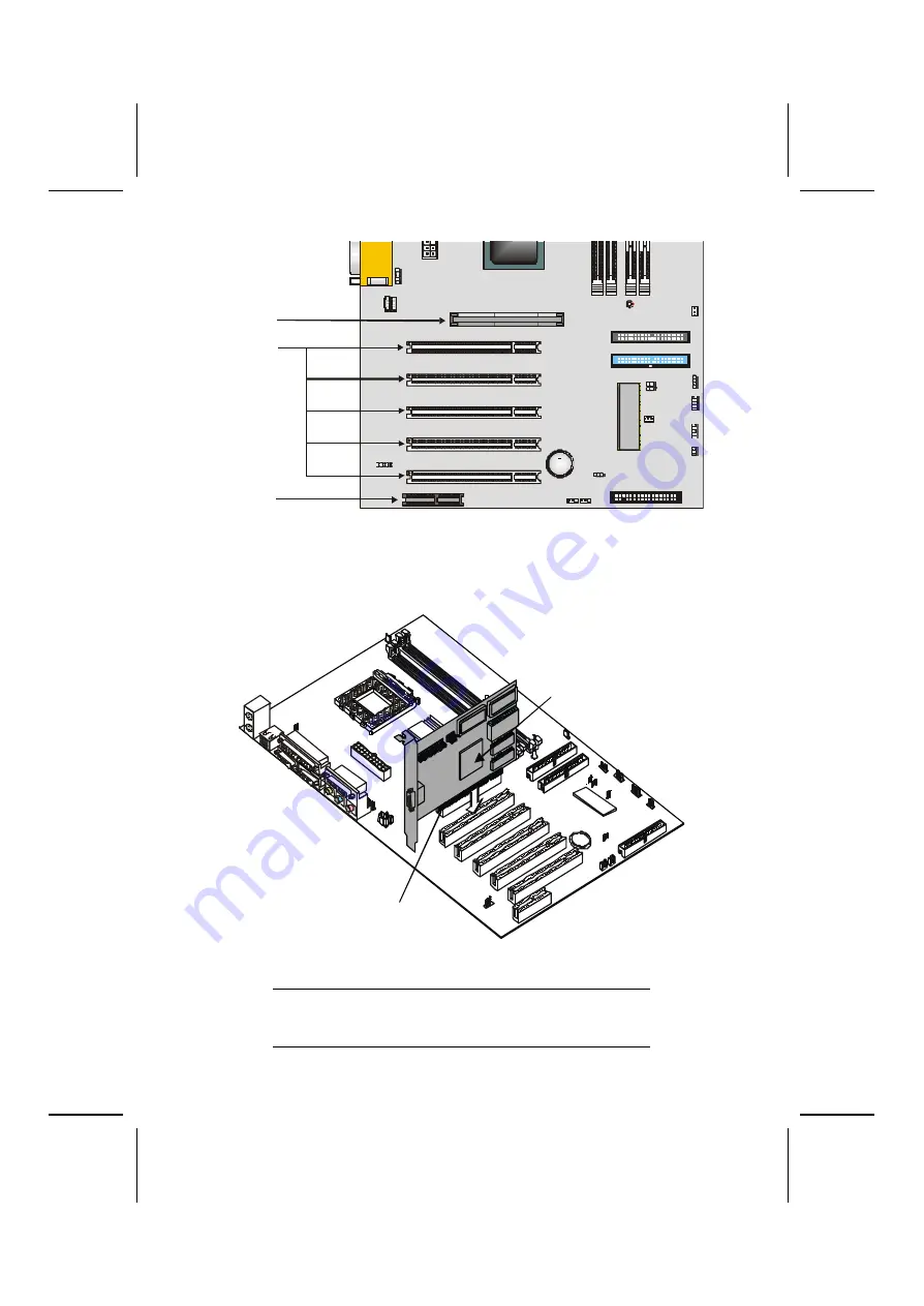
AGP slot
PCI slots

CNR slot


1.  Remove a blanking plate from the system case corre-

sponding to the slot you are going to use.  

2.  Install the edge connector of the add-on card into the 

expansion slot. Ensure that the edge connector is cor-
rectly seated in the slot.  

Edge connector

Add-on card


3.  Secure the metal bracket of the card to the system 

case with a screw. 

Note:

  For some add-on cards, for example graphics adapters 

and network adapters, you have to install drivers and 
software before you can begin using the add-on card. 

Содержание K7S5A2

Страница 1: ...h re spect to the contents hereof and specifically disclaims any implied warranties of merchantability or fitness for any particular purpose The manufacturer reserves the right to revise this publication and to make changes from time to time in the content hereof without obliga tion of the manufacturer to notify any person of such revision or changes Trademark Recognition Microsoft MS DOS and Wind...

Страница 2: ...s cause harmful interference to radio or television reception which can be determined by turning the equipment off and on the user is encouraged to try to correct the interference by one or more of the following measures Reorient or relocate the receiving antenna Increase the separation between the equipment and the receiver Connect the equipment onto an outlet on a circuit different from that to ...

Страница 3: ...ence and This device must accept any interference received includ ing interference that may cause undesired operation Canadian Department of Communications This class B digital apparatus meets all requirements of the Cana dian Interference causing Equipment Regulations Cet appareil numérique de la classe B respecte toutes les exigences du Réglement sur le matériel brouilieur du Canada ...

Страница 4: ...Go to page 1 Chapter 2 Installing the Mainboard Describes installation of main board components Go to page 8 Chapter 3 Using BIOS Provides information on using the BIOS Setup Utility Go to page 33 Chapter 4 Using the Mainboard Software Describes the mainboard soft ware Go to page 64 Appendix A Setting Jumpers Provides a reference to the jumpers on the mainboard Go to page 73 ...

Страница 5: ...umper Settings 11 Jumper Settings 12 Installing the Mainboard in a Case 14 Connecting Case Components 15 The Panel Connector 16 Installing Hardware 17 Installing the Processor 17 Install Memory Modules 20 Installing a Hard Disk Drive CD ROM 22 Installing a Floppy Diskette Drive 25 Installing Add on Cards 26 Connecting Optional Devices 28 Connecting I O Devices 31 External Connector Color Coding 32...

Страница 6: ... Option 61 Load Optimized Defaults Option 61 Set Password Option 62 Save Exit Setup Option 63 Exit Without Saving 63 CHAPTER 4 64 Using the Mainboard Software 64 About the Software CD ROM 64 Auto installing under Windows 98 65 Running Setup 66 Folders for this Mainboard 68 Utility Folder 68 K7S5A2 Folder 68 Utility Folder Installation Notes 69 Mainboard K7S5A2 Installation Notes 71 APPENDIX A 73 S...

Страница 7: ... up to 133 MHz The K7S5A2 incorporates the SiS735 Northbridge and South bridge chipsets which combine support for the new high bandwidth Double Data Rate DDR 266 SDRAM and the AC 97 audio codec Note SDRAM provides 800 MBps or 1 GBps data trans fer depending on whether the bus is 100 MHz or 133 MHz Double Data Rate SDRAM DDR SDRAM doubles the rate to 1 6 GBps or 2 1 GBps by transferring data on bot...

Страница 8: ... t Compare the mainboard s package contents with the following checklists Standard Items One mainboard One diskette drive ribbon cable and bracket One IDE drive ribbon cable and bracket One auto install software support CD This user s manual ...

Страница 9: ...ng a high speed connection to ATA 100 Hard Disk Drives delivering maximum sustained data transfer rates of 100 MB sec Built in multithreaded I O link used to enhance performance providing enough I O bandwidth for throughput up to 1 2 GB s Additional key features include support for six USB ports an AC 97 link for audio and modem hardware monitoring and ACPI OnNow power management Memory The mainbo...

Страница 10: ...ns Network Riser CNR slot AC97 interface only Two IDE channels and a floppy disk drive in terface The K7S5A2 supports Ultra DMA bus mastering with transfer rates of 33 66 100 MB sec Integrated I O The mainboard has a full set of I O ports and con nectors Two PS 2 ports for mouse and keyboard Two serial ports One parallel port One MIDI game port Two USB ports Audio jacks for microphone line in and ...

Страница 11: ...C D 1 A G P 1 P C I 1 P C I 2 P C I 3 P C I 4 P C I 5 C N R 1 B T 1 U S B 2 U S B 3 J P 1 W O L 1 W O M 1 S P K R 1 P A N E L 1 I R 1 F D D 1 J P 4 J P 3 C D 2 I D E 1 J P 2 1 1 1 1 1 1 1 1 1 1 AGP1 PCI1 PCI2 PCI3 PCI4 PCI5 CNR1 BT1 USB2 WOL1 WOM1 IR1 USB3 PANEL1 SPKR1 IDE1 DDR1 DDR2 SDR1 SDR2 CPU SOCKET CPUFAN1 ATX1 CD1 CD2 J2 PWRFAN1 PWRFAN2 FDD1 JP1 JP3 JP4 JP2 IDE2 LED1 ...

Страница 12: ...cable header J2 Front Audio Connector JP1 Clear CMOS jumper JP2 Keyboard and USB power on jumper JP3 BIOS protection jumper JP4 ROM type selection jumper LED1 1 Memory module LED PANEL1 Connector for case front panel switches and LED indicators PCI1 PCI5 Five 32 bit add on card slots PWRFAN1 Case fan connector 1 PWRFAN2 Case fan connector 2 SDR1 SDR2 Two 184 pin SDR SDRAM SPKR1 Speaker connector U...

Страница 13: ...orts all the features required The mainboard can support one or two floppy diskette drives and four enhanced IDE drives En sure that your case has sufficient power and space for all the drives that you intend to install Most cases have a choice of I O templates in the rear panel Make sure that the I O template in the case matches the I O ports installed on the rear edge of the mainboard This mainb...

Страница 14: ...lling the mainboard Wear a grounding strip attached to a grounded device to avoid damage from static electricity Discharge static electricity by touching the metal case of a safely grounded object before working on the mainboard Leave components in the static proof bags they came in Hold all circuit boards by the edges Do not bend cir cuit boards ...

Страница 15: ...lling Jumpers Go to page 10 Installing the Mainboard in a Case Go to page 14 Installing Case Components Go to page 15 Installing the CPU Go to page 17 Installing Memory Go to page 20 Installing an HDD and CD ROM Drive Go to page 22 Installing an FDD Go to page 25 Installing Add on Cards Go to page 26 Connecting Options Go to page 28 Connecting Peripheral I O Devices Go to page 31 Note The appendix...

Страница 16: ...tem configuration op tions Jumpers with more than one pin are numbered When setting the jumpers ensure that the jumper caps are placed on the correct pins Short Open This illustration shows a 2 pin jumper When the jumper cap is placed on both pins the jumper is SHORT If you remove the jumper cap or place the jumper cap on just one pin the jumper is OPEN 1 2 3 This illustration shows a 3 pin jumper...

Страница 17: ... illustration pin 1 is shown C PUFAN1 PWRFAN2 PWRF A N1 SDR1 D D R 1 D D R 2 SDR2 LED1 IDE2 ATX1 J 2 CD1 AGP1 PCI1 PCI2 PCI3 PCI4 PCI5 C N R 1 BT1 USB2 U SB3 JP1 WOL1 WOM1 SPKR1 PANEL1 IR1 FDD1 JP4 JP3 CD2 IDE1 JP2 1 1 1 1 1 1 1 1 1 1 JP3 JP2 JP1 JP4 1 1 1 1 ...

Страница 18: ...Jumper Type Description Setting default JP1 3 pin Clear CMOS 1 2 Normal 2 3 Clear JP1 1 JP2 3 pin KB Power ON 1 2 Enable 2 3 Disable JP2 1 JP3 3 pin BIOS protec tion 1 2 Disable 2 3 Enable JP3 1 JP4 3 pin ROM Type 1 2 5V 2 3 3V JP4 1 ...

Страница 19: ...mper if you want keyboard or USB activity to awaken the system from power saving mode Jumper 3 Enables you to prevent the BIOS from being up dated flashed Set the jumper to disabled if you are going to update your BIOS After updating the BIOS return it to the default setting en abled For instructions on updating the BIOS refer to Chapter 3 Jumper 4 Selects the voltage of the onboard ROM This jumpe...

Страница 20: ...s as this can stress the mainboard Most system cases have mounting brackets in stalled in the case which correspond to the holes in the mainboard Place the mainboard over the mounting brackets and secure the mainboard into the mounting brackets with screws 2 Secure the screws in the mainboard holes that align with the chassis holes 1 Place the mainboard over the case fasteners The mainboard has a ...

Страница 21: ...2 L E D 1 I D E 2 A TX 1 J 2 C D 1 AGP1 P C I 1 P C I 2 P C I 3 P C I 4 P C I 5 CNR1 BT1 U S B 2 U SB 3 J P 1 W O L 1 WOM1 S PK R 1 P A N E L1 I R 1 F D D 1 J P 4 J P 3 C D 2 I D E 1 J P 2 1 1 1 1 1 1 1 1 1 1 CPUFAN1 PWRFAN2 PWRFAN1 ATX1 PANEL1 1 1 Connect the case power supply connector to ATX1 2 Connect the CPU cooling fan cable to CPUFAN1 3 Connect the case cooling fan connector to either PWRFA...

Страница 22: ...TX cases Refer to the table below for information Device Pins Empty 10 N C 9 Power ON OFF 6 8 Reset Switch 5 7 Green LED Indicator 2 4 HDD LED 1 3 HDD LED Pins 1 3 2 1 Reset Switch Pins 5 7 Power Switch Pins 6 8 Green LED Pins 2 4 Empty Pin 10 10 9 N C Pin 9 Note The plus sign indicates a pin which must be con nected to a positive voltage ...

Страница 23: ...s sor socket Before installing the Processor This mainboard automatically determines the CPU clock fre quency and system bus frequency for processor You may be able to change these automatic settings by changing the set tings in the system Setup Utility We strongly recommend that you do not overclock the mainboard to run processors or other components faster than their rated speed Warning Overcloc...

Страница 24: ...socket locking lever away from the socket to unhook it and raise the locking lever to the upright position 2 Identify the pin A 1 corner on the CPU socket and the pin A 1 corner on the processor 3 Match the pin A 1 corners and insert the processor into the socket Do not use force 4 Swing the locking lever down and hook it under the latch on the edge of the socket 5 Apply thermal grease to the top ...

Страница 25: ...atsink assembly Pin 1 corners CPU fan connector 6 Lower the CPU fan heatsink unit onto the CPU and CPU socket and then snap the fan heatsink into place 7 Plug the CPU fan power cable into the CPU cooling fan power supply on the mainboard CPUFAN1 ...

Страница 26: ...f memory modules simultaneously The memory bus can run at 100 MHz or 133 MHz If your processor operates over a 100 MHz system bus you can in stall PC100 or PC133 memory modules that operate over a 100 MHz or 133 MHz memory bus If your processor operates over a 133 MHz system bus you can only install PC133 memory modules that operate over a 133 MHz memory bus Note SDRAM provides 800 MBps or 1 GBps ...

Страница 27: ...s Each module can be installed with 32 MB to 512 MB of memory to tal memory capacity is 1 GB 1 Align the memory module with the slot The DIMM slots are keyed with notches and the DIMMs are keyed with cutouts so that they can only be installed correctly Check that the cutouts on the DIMM module edge connector match the notches in the DIMM slot ...

Страница 28: ...E channel in terface IDE1 and IDE2 An IDE ribbon cable supporting two IDE devices is bundled with the mainboard IDE devices have jumpers or switches that are used to set the IDE device as MASTER or SLAVE Refer to the IDE device user s manual If you want to install more than two IDE devices get a second IDE cable and you can add two more devices to the secon dary IDE channel When installing two IDE...

Страница 29: ...ke sure that you match the pin 1 side of the cable connector with the pin 1 side of the device connector Each connector has the pin 1 side clearly marked The pin 1 side of each ribbon cable is always marked with a colored stripe on the cable 3 Plug an IDE cable connector into the hard disk drive IDE connector It doesn t matter which connector on the cable you use Ensure that the pin 1 side of the ...

Страница 30: ...If you have already in stalled an HDD you can use the free connector on its IDE cable B Note Ribbon cable connectors are usually keyed so that they can only be installed correctly on the device connector If the connector is not keyed make sure that you match the pin 1 side of the cable connector with the pin 1 side of the device connector Each connector has the pin 1 side clearly marked The pin 1 ...

Страница 31: ...that you have installed See Chapter 3 for more information Installing a Floppy Diskette Drive The mainboard has a floppy diskette drive FDD interface ships with a diskette drive ribbon cable that supports one or two floppy diskette drives You can install a 5 25 inch drive and a 3 5 inch drive with various capacities The floppy disk ette drive cable has one type of connector for a 5 25 inch drive a...

Страница 32: ...t up your system go immediately to the Setup Utility and use the Standard page to configure the floppy diskette drives that you have installed See Chapter 3 for more information Installing Add on Cards This mainboard has five 32 bit PCI Peripheral Components Interconnect expansion slots one 4xAGP slot and one Communications and Networking Riser CNR slot PCI Slots PCI slots are used to install expa...

Страница 33: ... system case corre sponding to the slot you are going to use 2 Install the edge connector of the add on card into the expansion slot Ensure that the edge connector is cor rectly seated in the slot Edge connector Add on card 3 Secure the metal bracket of the card to the system case with a screw Note For some add on cards for example graphics adapters and network adapters you have to install drivers...

Страница 34: ...I2 PCI3 PCI4 PCI5 CNR1 BT1 USB2 U SB3 JP1 WOL1 WOM1 S PKR1 PANE L1 IR1 FDD1 JP4 JP3 CD 2 IDE1 JP2 1 1 1 1 1 1 1 1 1 1 J2 USB2 USB3 WOL1 WOM1 IR1 SPEAKER1 1 1 1 1 1 1 J2 Front Audio Connector This connector is used to attach to Audio equipment embed ded into or attached to the case Pin Signal Name Pin Signal Name 1 3 5 7 9 AUD_MIC MIC_BIAS AUD_F_R RESERVED AUD_F_L 2 4 6 8 10 AUD_GND AUD_VCC AUD_RET...

Страница 35: ...ou have installed a LAN card use the cable provided with the card to plug into the mainboard WOL1 connector This en ables the Wake On LAN WOL feature When your system is in a power saving mode any LAN signal automatically re sumes the system You must enable this item using the Power Management page of the Setup Utility Pin Signal Name 1 2 3 5VSB Ground SENSE If you have installed a modem use the c...

Страница 36: ...on between your computer and similarly equipped devices such as printers laptops Personal Digital Assistants PDAs and other com puters Pin Signal Name Pin Signal Name 1 3 5 N A 5V IRTX CIRTX 2 4 6 KEY GND IRRX CIRRX SPEAKER1 Internal speaker Connect the internal speaker connector to this header Pin Signal Name 1 2 3 4 SPKR NC Ground 5V ...

Страница 37: ... connect a PS 2 keyboard 2 Use the USB ports to connect USB devices 3 Use LPT1 to connect printers or other parallel commu nications devices 4 Use the COM ports to connect serial devices such as mice or fax modems COM1 is identified by the system as COM1 3 COM2 is identified by the system as COM2 4 5 Use the game port to connect a joystick or a MIDI de vice 6 Use the three audio ports to connect a...

Страница 38: ...e Audio line out Lime Digital monitor flat panel White IEEE 1394 Grey Microphone Pink MIDI Game Gold Parallel Burgundy PS 2 compatible keyboard Purple PS 2 compatible mouse Green Serial Teal or Turquoise Speaker out subwoofer Orange Right to left speaker Brown USB Black Video out Yellow SCSI network telephone modem None This concludes Chapter 2 Chapter 3 covers the BIOS ...

Страница 39: ...n battery backed up CMOS RAM that saves this information even when the power is turned off When the system is turned back on the system is configured with the values found in CMOS The BIOS Setup Utility enables you to configure Hard drives diskette drives and peripherals Video display type and display options Password protection from unauthorized use Power management features The settings made in ...

Страница 40: ...d to make any changes in the future This Setup Utility should be used when changing the system configuration when a configuration error is detected and you are prompted to make changes to the Setup Utility when trying to resolve IRQ conflicts when making changes to the Power Management con figuration when changing the password or making other changes to the Security Setup ...

Страница 41: ...er Management Setup PnP PCI Configurations PC Health Status Frequency Voltage Control Load Fail Safe Defaults Load Optimized Defaults Set Password Save Exit Setup Exit Without Saving Esc Quit Select Item F10 Save Exit Setup Time Date Hard Disk Type BIOS Navigation Keys The BIOS navigation keys are listed below Key Function Esc Exits the current menu Scrolls through the items on a menu PU PD Modifi...

Страница 42: ...e sys tem diskette you created in Step 3 5 Turn off your computer and insert the system diskette in your computer s diskette drive You might need to run the Setup Utility and change the boot priority items on the Advanced BIOS Features Setup page to force your computer to boot from the floppy diskette drive first 6 At the A prompt type the Flash Utility program name and press Enter You see a scree...

Страница 43: ...the option Use the cursor arrow keys to scroll through the items in the submenu In this manual default values are enclosed in parenthesis Submenu items are denoted by a triangle Standard CMOS Features This option displays a table of items defining basic information about your system CMOS Setup Utility Copyright C 1984 2001 Award Software Standard CMOS Features Item Help Date mm dd yy Tue July 11 2...

Страница 44: ...omp 0 Landing Zone 0 Sector 0 Menu Level To auto detect the HDD s size head on this channel Move Enter Select PU PD Value F10 Save ESC Exit F1 General Help F5 Previous Values F6 Fail Safe Defaults F7 Optimized Defaults IDE HDD Auto Detection Press Enter while this item is highlighted to prompt the Setup Utility to automatically detect and configure an IDE de vice on the IDE channel Note If you are...

Страница 45: ...ard CMOS Features page Drive A Drive B 1 44M 3 5 in None These items define the characteristics of any diskette drive at tached to the system You can connect one or two diskette drives Floppy 3 Mode Support Disabled Floppy 3 mode refers to a 3 5 inch diskette with a capacity of 1 2 MB Floppy 3 mode is sometimes used in Japan Video EGA VGA This item defines the video mode of the system This main bo...

Страница 46: ...M 64MB Non OS2 Menu Level Allows you to choose the VIRUS warning feature for IDE Hard Disk boot sector protection If this function is enabled and someone attempts to write data into this area BIOS will show a warning message on screen and alarm beep Move Enter Select PU PD Value F10 Save ESC Exit F1 General Help F5 Previous Values F6 Fail Safe Defaults F7 Optimized Defaults Anti Virus Protection D...

Страница 47: ... shorten the power on testing POST and have your system start up faster You might like to enable this item after you are confident that your system hardware is op erating smoothly 1st 2nd 3rd Boot Device Floppy HDD 0 LS120 Use these three items to select the priority and order of the devices that your system searches for an operating system at start up time Boot Other Device Enabled When enabled t...

Страница 48: ...ematic Rate Chars Sec Use this item to define how many characters per second are generated by a held down key Typematic Delay Msec Use this item to define how many milliseconds must elapse before a held down key begins generating repeat characters Security Option Setup If you have installed password protection this item defines if the password is required at system start up or if it is only re qui...

Страница 49: ... status of the drive If a device failure is predicted the host software through the Client WORKS S M A R T applet warns the user of the im pending condition and advises appropriate action to protect the data Report No FDD For WIN95 Yes If you are running a system with no floppy drive and using Windows 95 select Yes for this item to ensure compatibility with the Windows 95 logo certification Otherw...

Страница 50: ...tly you may introduce fatal er rors or recurring instability into your system CMOS Setup Utility Copyright C 1984 2001 Award Software Advanced Chipset Features Item Help Advanced DRAM Control 1 Press Enter Advanced DRAM Control 2 Press Enter Memory Hole at 15M 16M Disabled AGP Fast Write control Enabled AGP Data Transfer Rates Support 4X AGP Aperture Size 64MB PCI SLOT 5 Support Enabled Menu Level...

Страница 51: ...us Values F6 Fail Safe Defaults F7 Optimized Defaults Auto Configuration Normal Mode This is the DRAM auto configuration option which can be set to Safe Mode Normal Mode Fast Mode or Ultra Mode CPU DRAM CLK Synch CTL AUTO This option allows you set the CPU DRAM synchronization The valid options are AUTO Synchronous and Asynchronous DRAM BackGround Cycles Delay 1T This option allows you to set the ...

Страница 52: ... Valid values are 05 ns 1 0 ns 1 5 ns and 2 0 ns DQS CSB Hold Time CTL 0 5 ns This option allows you to set the DQS CSB Hold Time Valid values are 05 ns 1 0 ns 1 5 ns and 2 0 ns CKE Hold Time CTL 0 5 ns This option allows you to set the CKE Hold Time Valid values are 05 ns 1 0 ns 1 5 ns and 2 0 ns Memory Hole at 15M 16M Disabled This item is used to reserve memory space for ISA expansion cards tha...

Страница 53: ...rt for this mainboard Integrated Peripherals Option This option displays a list of items that defines the operation of peripheral components on the system s input output ports CMOS Setup Utility Copyright C 1984 2001 Award Software Integrated Peripherals Item Help SIS OnChip IDE Device Press Enter SIS OnChip PCI Device Press Enter Onboard SuperI O Device Press Enter USB Controller Enabled USB keyb...

Страница 54: ...hat are integrated on the mainboard IDE Primary Secondary Master Slave PIO Auto Each IDE channel supports a master device and a slave de vice These four items let you assign which kind of PIO Programmed Input Output is used by IDE devices Choose Auto to let the system auto detect which PIO mode is best or select a PIO mode from 0 4 IDE Primary Secondary Master Slave UltraDMA Auto Each IDE channel ...

Страница 55: ... Value F10 Save ESC Exit F1 General Help F5 Previous Values F6 Fail Safe Defaults F7 Optimized Defaults SIS 7012 7018 AC97 AUDIO Enabled Enables and disables the onboard audio chip Disable this item if you are going to install a PCI audio add on card SIS 7013 S W Modem Auto Enables and disables the onboard modem Disable this item if you are going to install an external modem IDE ACCESS INTERFACE E...

Страница 56: ...e Enter Select PU PD Value F10 Save ESC Exit F1 General Help F5 Previous Values F6 Fail Safe Defaults F7 Optimized Defaults Onboard FDC Controller Enabled This option enables the onboard floppy disk drive controller Onboard Serial Port 1 3F8 IRQ4 This option is used to assign the I O address and interrupt re quest IRQ for onboard serial port 1 COM1 Onboard Serial Port 2 2F8 IRQ3 This option is use...

Страница 57: ... your parallel port There are four options SPP Standard Parallel Port EPP Enhanced Parallel Port ECP Extended Capabilities Port and ECP EPP SPP allows data output only Extended Capabilities Port ECP and Enhanced Parallel Port EPP are bi directional modes a l lowing both data input and output ECP and EPP modes are only supported with EPP and ECP aware peripherals ECP Mode Use DMA 3 When the onboard...

Страница 58: ...r disable the AGP buffer strength auto calibration through the chipset Power Management Setup Option This option displays items that let you control the system power management Modern operating systems take care of much of the power management This mainboard supports ACPI Advanced Configuration and Power Interface The sys tem has various power saving modes including powering down the hard disk tur...

Страница 59: ...SC Exit F1 General Help F5 Previous Values F6 Fail Safe Defaults F7 Optimized Defaults ACPI Function Enabled This mainboard supports ACPI Advanced Configuration and Power management Interface Use this item to enable or dis able the ACPI feature Note ACPI is a power management specification that makes hardware status information available to the operating system ACPI enables a PC to turn its pe rip...

Страница 60: ...rom a power saving mode use this item to specify the interrupt request line IRQ that is used by the mo dem You might have to connect the fax modem to the mainboard Wake On Modem connector for this feature to work Hot Key Function As Power Off This option allows you to set the Hot Key functionality to one of the following states Disable turn off Hot Key functionality Power Off Suspend HDD Off After...

Страница 61: ...item is set to Delay 4 Sec then you have to hold the power button down for four seconds to cause a software power down Power State Resume Control Always Off This sets the power state after a shutdown due to an unex pected interrupt of AC power ...

Страница 62: ...F7 Optimized Defaults This item opens a submenu that enables you to set events that will resume the system from a power saving mode IRQ 3 7 9 15 NMI Enabled This option determines whether any activity for IRQ 3 7 9 15 will cause the system to wake from a power saving mode IRQ 8 Break Suspend Determines whether the system will monitor IRQ 8 activity and wake the system from a power saving mode when...

Страница 63: ...OS Setup Utility Copyright C 1984 2001 Award Software PnP PCI Configurations Item Help Reset Configuration Data Disabled Resources Controlled by Auto ESCD x IRQ Resources Press Enter PCI VGA Palette Snoop Disabled INT Pin 1 Assignment Auto INT Pin 2 Assignment Auto INT Pin 3 Assignment Auto INT Pin 4 Assignment Auto Menu Level Default is Disabled Select Enabled to reset Extended System Con figurat...

Страница 64: ...rces submenu In the Memory Resources submenu use the first item R e served Memory Base to set the start address of the memory you want to reserve for the ISA expansion card Use the sec ond item Reserved Memory Length to set the amount of reserved memory Press Esc to close the Memory Re sources submenu PCI VGA Palette Snoop Disabled This item is designed to overcome some problems that can be caused...

Страница 65: ...CPU Core Voltage Vcc 2 5V Vcc 3 3V Vcc 5 0V 12V StandBy 3 3V StandBy 5 0V Voltage Battery System Temperature CPU Temperature CPU FAN speed PWR Fan1 Speed PWR Fan2 Speed Menu Level MoveEnter Select PU PD Value F10 Save ESC Exit F1 General Help F5 Previous Values F6 Fail Safe Defaults F7 Optimized Defaults Shutdown Temperature Enables you to set the maximum temperature the system can reach before po...

Страница 66: ... F5 Previous Values F6 Fail Safe Defaults F7 Optimized Defaults Auto Detect DIMM PCI Clk Enabled When this item is enabled BIOS will disable the clock signal of free DIMM and PCI slots Spread Spectrum Enabled If you enable spread spectrum it can significantly reduce the EMI Electro Magnetic Interference generated by the system CPU Host Clock CPU PCI Default Use the CPU Host Clock to set the fronts...

Страница 67: ... fail safe defaults for a specific option select and display that op tion and then press F6 Load Optimized Defaults Option This option opens a dialog box that lets you install optimized defaults for all appropriate items in the Setup Utility Press Y and then Enter to install the defaults Press N and then Enter to not install the defaults The optimized defaults place demands on the system that may ...

Страница 68: ...iates be tween upper case and lower characters Press Enter after you have typed in the password If you are deleting a password that is already installed just press Enter when the password dialog box appears You see a message that indicates that the password has been disabled PASSWORD DISABLED Press any key to continue 4 Press any key You are prompted to confirm the pass word Confirm Password 5 Typ...

Страница 69: ...ht this item and press Enter to discard any changes that you have made in the Setup Utility and exit the Setup Util ity When the Exit Without Saving dialog box appears press Y to discard changes and exit or press N to return to the main menu Note If you have made settings that you do not want to save use the Exit Without Saving item and press Y to discard any changes you have made This concludes C...

Страница 70: ...nd a brief description of each software program and the lo cation for your mainboard version More information on some programs is available in a README file located in the same directory as the software Note Never try to install software from a folder that is not specified for use with your mainboard Before installing any software always inspect the folder for files named README TXT INSTALL TXT or...

Страница 71: ...dows Ex plorer Refer to Utility Folder Installation Notes later in this chapter The support software CD ROM disc loads automatically under Windows 98 When you insert the CD ROM disc in the CD ROM drive the autorun feature will automatically bring up the install screen The screen has three buttons on it Setup Browse CD and Exit Note If the opening screen doesn t appear double click the file setup e...

Страница 72: ... software correctly Some software is installed in separate folders for different op erating systems such as DOS WIN NT or WIN98 95 Always go to the correct folder for the kind of OS you are using To install the software execute a file named SETUP EXE or INSTALL EXE by double clicking the file and then following the instructions on the screen Exit The Exit button closes the Auto Setup window Runnin...

Страница 73: ...following screen appears 3 Check the box next to the items you want to install The default options are recommended 4 Click Next run the Installation Wizard An item installa tion screen appears 5 Follow the instructions on the screen to install the items Drivers and software are automatically installed in sequence Follow the onscreen instructions confirm commands and a l low the computer to restart...

Страница 74: ...st Simulates up to twenty three 200X CD ROM drives MEDIARING TALK Telephony software Recovery Gen ius Data recovery software 30 day trial ver sion SUPER VOICE Fax modem software K7S5A2 Folder Use the software in the following sub folders AUDIO This folder contains a short README file giving directions to alternate folders for installing the audio software LAN This folder contains a short README fi...

Страница 75: ...ust be in real mode DOS not the DOS box that is avail able in Windows 98 95 NT If you are using WINDOWS 98 95 shut down your computer and select the option Restart in DOS in the shutdown dialog box If you are running Windows NT shut down your computer and boot from a DOS diskette temporarily in order to run the flash memory utility CD Ghost The CD Ghost software enables you to create a virtual cab...

Страница 76: ...deletions and from system cor ruption To install the Recovery Genius software program run SETUP EXE from the following directory UTILITY RECOVERY GENIUS ENG RECOVERYGENIUS Super Voice To install the Super Voice voice fax data communication ap plication for use with the built in fax modem go the directory UTILITY SUPERVOICE then run PICSHELL EXE to install the application software ...

Страница 77: ...stallation for Windows 2000 ME 98SE 95 To install the audio drivers run SETUP EXE from the following directory SiS 635CODEC Installation for Windows NT4 0 1 Click Start 2 Click Settings and then click Control Panel 3 Double click the Multimedia icon 4 Select the Devices tab 5 Click Add 6 Select the item Unlisted or Updated Driver in the List of Drivers in the list box and then specify the path to ...

Страница 78: ...TUP EXE from the following directory SiS LANSiS900 VGA Software The enhanced VGA drivers for the K7S5A2 are in the SiS VXD folder Drivers are supplied for Windows 2000 98 ME Installation for Windows ME 98 To install the IDE drivers run SETUP EXE from the following directory SiS VXD WIN9X Installation for Windows 2000 To install the IDE drivers run SETUP EXE from the following directory SiS VXD WIN...

Страница 79: ...umper Settings Jumper Type Description Setting default JP1 3 pin Clear CMOS 1 2 Normal 2 3 Clear JP1 1 JP2 3 pin KB Power ON 1 2 Enable 2 3 Disable JP2 1 JP3 3 pin BIOS protec tion 1 2 Disable 2 3 Enable JP3 1 JP4 3 pin ROM Type 1 2 5V 2 3 3V JP4 1 ...

Страница 80: ...mper if you want keyboard or USB activity to awaken the system from power saving mode Jumper 3 Enables you to prevent the BIOS from being up dated flashed Set the jumper to disabled if you are going to update your BIOS After updating the BIOS return it to the default setting en abled For instructions on updating the BIOS refer to Chapter 3 Jumper 4 Selects the voltage of the onboard ROM This jumpe...

Страница 81: ...TX cases Refer to the table below for information Device Pins Empty 10 N C 9 Power ON OFF 6 8 Reset Switch 5 7 Green LED Indicator 2 4 HDD LED 1 3 HDD LED Pins 1 3 2 1 Reset Switch Pins 5 7 Power Switch Pins 6 8 Green LED Pins 2 4 Empty Pin 10 10 9 N C Pin 9 Note The plus sign indicates a pin which must be con nected to a positive voltage ...

Отзывы: