


12052022JA
7
www.elitescreens.com
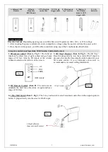
A. Infrared (IR)
Remote
B. Radio
Frequency
(RF) Remote
C. Wall switch
control box
D. 5-12 volt
trigger cable
E. IR extended
“eye” receiver
F. Wireless 5-
12v (3.5mm)
mono to USB
trigger cable
G. AAA
batteries
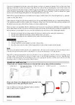
Screen operation
Electric Current
: Depending upon region, your Elite Screen will operate on 100v, 110v, or 220v voltage.
1. After ensuring the power outlet & screen are compatible (voltage), plug the power cord into the power outlet.
2. Once the screen has power, you’ll be able to control it using any of the 6 methods described below.
6 ways to control your Spectrum Tab-Tension 2 motorized screen
1. IR remote control
(
Item A, Fig 1
): The Infrared
functions by direct line of sight contact using a beam
range of 30 feet. Aim the IR remote at the circular
window located on the left side of the screen.
2. RF Remote Control
(
Item B
): The radio waves
eliminate the need for a direct line of sight and has a
range of 100 feet.
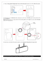
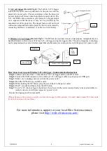
3. IR “Eye” Receiver
(
Item E, Fig 2
): The IR “Eye”
Receiver plugs directly into the screen’s RJ-45 input to
present a low-profile line-of-sight control option for your
IR remote control. It is an extended eye-receiver to
accommodate a recessed ceiling installation.
4. 3-Way Wall Switch
(
Item C, Fig 3
): The 3-way wall switch is a wall mounted control box with an up/stop/down
button. It plugs directly into the screen’s RJ-45 input.
UP
STOP
DOWN
Fig.1
IR/RF remote
IR “eye” receiv
er
Fig.2
3 Way Wall Switch
(does not have IR sensor)
Fig.3