background image

 Wireless Solutions

48 Mivtza Kadesh St. Bene Beraq 51203 , ISRAEL                         Tel: +972-3-6175639 Fax:+972-3-6175962

3  RI 

HPDLO  [email protected]

:HE VLWH ZZZPZHOLVUDFRP

5HY%

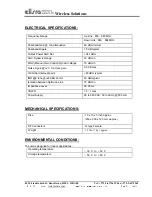
ELECTRICAL SPECIFICATIONS:

Frequency Range

Up Link : 835

849 MHz

Down Link : 880

894 MHz

Passband Gain @ min attenuation

60 dB minimum

Passband Ripple

1.5 dB typical

Output Power AGC Set

+24 1 dBm

AGC Dynamic Range

30 dB min

MGC (Manual Gain Control) Dynamic Range

15 dB min

Noise Figure @+25 C at max gain

6.0 dB max

3rd Order Intercept point

+45 dBm typical

IMD @2 tone @+20 dBm/carrier

50 dBc typical

Isolation between Up/Down Link

75 dB min

Impedance Level

50 Ohms

VSWR

1.5 : 1 max

Power Supply

80 to 240 VAC; 50 to 60 Hz; @500 mA

MECHANICAL SPECIFICATIONS:

Size

: 10 x 10 x 5 inch approx.

 (250 x 250 x 120 mm approx.)

RF Connectors

: N-type Female

Weight

: 15 Lbs. (7 kg.) approx.

ENVIRONMENTAL CONDITIONS:

The unit is designed for indoor applications:

Operating temperature

: - 30 C  to  + 50 C

Storage temperature

: - 50 C  to  + 80 C

Содержание MW-CBDA-TDMAB-1W60-A

Страница 1: ...za Kadesh St Bene Beraq 51203 ISRAEL Tel 972 3 6175639 Fax 972 3 6175962 3 RI HPDLO trm1 elisra com HE VLWH ZZZ PZ HOLVUD FRP 5HY INSTALLATION AND OPERATING INSTRUCTIONS FOR MW CBDA TDMAB 1W60 A CELLULAR BI DIRECTIONAL AMPLIFIER ...

Страница 2: ...OLVUD FRP 5HY TABLE OF CONTENTS PARAGRAPH PAGE No BDA OVERVIEW 3 BLOCK DAIGRAM DESCRIPTION 3 BDA OPERATION 4 AGC MGC FUNCTION 5 RF EXPOSURE WARNING 6 ELECTRICAL SPECIFICATIONS 7 MECHANICAL SPECIFICATIONS 7 ENVIRONMENTAL CONDITIONS 7 LIST OF DRAWINGS DRAWING PAGE No BDA WITH AGC RF BLOCK DIAGRAM DRAWING 4 AGC MGC CONTROL 5 MECHANICAL OUTLINE 8 ...

Страница 3: ...its them to the subscriber The BDA Uplink path receives the RF signals from the subscriber amplifies them and transmits them to the base station Two duplexers frequency separate the signals to the proper amplifying path and isolate the two signals For each path there is an AGC amplifier The amplifier has an AGC option switch When switched on the AGC circuit limits the amplifier output power The AG...

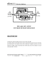
Страница 4: ...red by the BDA The isolation between the base station antenna and the mobile antenna should be at least 12 dB higher than the BDA gain If the isolation were less than the BDA gain oscillation would start and would saturate the amplifier Isolation few dB higher than the BDA gain cannot start oscillations but would causes gain ripple in the band XSOH HU RZQOLQN XSOH HU 8SOLQN 72 6 67 7 21 17 11 72 5...

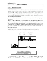
Страница 5: ...th when the AGC is On and when the AGC is OFF The switch on the RF amplifier enables the AGC function If the AGC is disabled then the amplifier gives maximum gain MGC The RF gain of the BDA can be reduced by about 15 dB using the continuos trimmer on the amplifier The RF gain is at maximum when the trimmer is at anti clockwise direction To reduce the gain turn the trimmer clockwise using a screwdr...

Страница 6: ...s about 10 dBi gain Typical specifications gain 8 dBd 10 1 dBi VSWR better than 1 5 1 Impedance 50 ohm The outdoor antenna must be installed to provide a minimum separation distance of 0 3 m 30 cm from persons within the area The second antenna is connected via cable that has typical 1 10 dB attenuation depends on the length of the cable to the CBDA MOBILE port This type of antenna is omnidirectti...

Страница 7: ...in MGC Manual Gain Control Dynamic Range 15 dB min Noise Figure 25 C at max gain 6 0 dB max 3rd Order Intercept point 45 dBm typical IMD 2 tone 20 dBm carrier 50 dBc typical Isolation between Up Down Link 75 dB min Impedance Level 50 Ohms VSWR 1 5 1 max Power Supply 80 to 240 VAC 50 to 60 Hz 500 mA MECHANICAL SPECIFICATIONS Size 10 x 10 x 5 inch approx 250 x 250 x 120 mm approx RF Connectors N typ...

Страница 8: ...Wireless Solutions 48 Mivtza Kadesh St Bene Beraq 51203 ISRAEL Tel 972 3 6175639 Fax 972 3 6175962 3 RI HPDLO trm1 elisra com HE VLWH ZZZ PZ HOLVUD FRP 5HY MECHANICAL OUTLINE ...

Отзывы: