7
IMPORTANT. Check to be sure that holes locations are
leveled, and correctly centered by the vertical centerline.
(This installation instruction applies for concrete wall).
Drill 5/16” pilot holes in the marked locations.
Install wall fastener anchors.
Drive wood screws, by hand, into the fasteners to allow
anchors to expand. Remove screws.
Secure the bracket to the wall with wood screws and/or
fasteners.
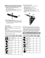
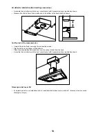
Option B - Telescopic duct cover
The duct bracket should be installed against the back wall
and flush with the ceiling. This bracket will hold the duct
cover in place at the top (this a extra accessory available
not included with the hood).
•
•
•
•
•
Ceiling
Vertical centerline
Wall
Duct piece
Dimensions
Equivalent
Lenght
Quantity
Used
Total
Equivalent
Lenght
Round,
straight
1 ft. (per foot
lenght)
3-1/4” x 12”,
3-1/4” x 24”
straight
1 ft. (per foot
lenght)
8” round, 90°
elbow
15 ft.
8” round, 45°
elbow
8 ft.
3 - 1/4” x 12”,
90° elbow
11 ft.
3 - 1/4” x 12”
or 45° elbow
6 ft.
3 - 1/4” x 12”,
90° flat elbow
24 ft.
8” round to
3-1/4” x 12” or
3-1/4” x 24”
transition
1 ft.
Duct piece
Dimensions
Equivalent
Lenght
Quantity
Used
Total
Equivalent
Lenght
3-1/4” x 12”
to 8” round
transition
8ft.
8” round to
3-1/4” x 12” or
transition 90°
elbow
16 ft.
3-1/4” x 12”
to 8” round
transition 90°
elbow
17 ft.
8” round
wall cap with
damper
30 ft.
3-1/4” x 12”
wall cap with
damper
30 ft.
8” round roof
cap
26 ft.
8” round roof
vent
26 ft.
DUCT FITTINGS
Use this chart to compute maximum permissible lengths for
ducts runs to outdoors.
NOTE:
Do not exceed maximum permissible equivalents
lengths!
Flexible ducting:
If flexible metal ducting is used, all the equivalent feet values
in the table should be doubled. The flexible metal duct should
be straight and smooth and extended as much as possible.
DO NOT
use flexible plastic ducting.
NOTE:
Any home ventilation system, such as a ventilation
hood, may interrupt the proper flow of combustion air and ex
-
haust required by fireplaces, gas furnaces, gas water heaters
and other naturallly vented systems. To minimize the chance
of interruption of such naturally vented systems, follow the
heating equipment manufacturer’s guidelines and safety stan-
dards such as those published by NFPA and ASHERAE.
This hood must use an 8” round duct.
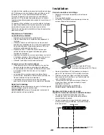
Secure the bracket to the wall:
Align the marked centerline on the bracket with the
centerline on the wall.
Mark 2 screw hole locations in the wall.
Drill 5/16” pilot holes in the marked locations.
Install wall fastener anchors.
Drive wood screws, by hand, into the fastener to allow
anchors to expand. Remove the screws.
Secure the bracket to the wall with wood screws and/or
fasteners.
•
•
•
•
•
•
Содержание ETB436SS
Страница 44: ...LI30NA Ed 10 11 Printed in Mexico ...


