

O
N
1
2
主體固定板
lock
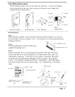
Step 4: Select the correct voltage and
delay time
※
Voltage Selection Jumper
Body
+V
Power Input
—
V
+V
Power I nput
—
V
Armature
COM
N. O.
N. C.
N. O
.
COM
N. C.
Primary Standard
Time Delay Switch
Blade Stop
Door
0.0sec
5.0sec
2.5sec
9.0sec
S2
Power
Supply
V+
V-
P.S
0.0 SEC
2.5 SEC
Mounting Plate
Exit
Bu tt on
N.O
5.0 SEC
9.0 SEC
Voltag e Selec t
12V 24V
COM .
N.C
1
2
ON
Monitor Output
Autolock Delay
Time Settings
Armature
※
Monitor output (0.5A) will change to N.O. point when
magnetic lock and armature are engaged (Red light of indicator
Rubber Washer
will change to green light )
Door leaf
[Installation diagram]
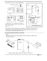
Step 5 :
Fix the magnet to the mounting (screws for fitting are included in the magnetic body)
and ensure the armature close lightly against the magnet when the door is closed to
avoid damage to the mating surface unnecessary.
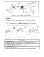
[In-swing door] (Bracket shall be used to install)
Step 1 :
Fix the magnet in the door jamb and fix the armature with the L.Z. bracket in the
door leaf. (as follow)
Outdoor
Indoor
※
( Setting of voltage, please refer to out-swing door
『
Step 4
』
)
Page 3


