


ISL55180 EVM Getting Started
Rev A04: 11/28/2012
Copyright
Elevate Semiconductor Corporation 2012
Page 7 of 20
2 Getting
Started
The ISL55180 EVM is shipped in a pre-configured state that allows a customer to evaluate the DPS
Force Voltage/Measure Current (FV/MI), Ganging and other features.
Note: Any external equipment providing digital signals into the ISL55180 device should only be enabled
after the ISL55180 EVM is enabled. Also, the external equipment should be disabled prior to disabling
the ISL55180 EVM.
2.1 Caution
The ISL55180 DUT Power Supply (DPS) is capable of delivering a couple amps of current. Configuring
the ISL55180 device and EVM into an extremely high power condition could cause permanent damage to
the ISL55180 device, EVM components and/or external equipment.
2.2 Quick Start Instructions
2.2.1 Default Power Supply Option
1. Disable external power supply
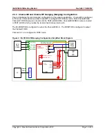
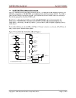
2. Connect the power supplies cables (not provided) from the power supply to the Elevate
Semiconductor EVM Motherboard and ISL55180 loadboard; refer to Figure 3.
3. Connect the parallel cable (provided) from the PC to J2 on the Octal FVMI board.
4. Connect the EVM to any external equipment; refer to Section 2.3.
5. Setup Motherboard Jumpers; refer to Section 2.4
6. Ensure Jumpers E4 and E5 are installed on the loadboard.
7. Ensure Jumpers E2 and E3 are shorting pins 1 and 2 (towards back of board).
8. Set external power supply voltages and current limits.
9. Enable external power supply.
10. Run the Elevate Semiconductor GUI software; refer to Section 1.3.4 for details.
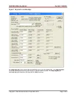
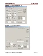
11. At the Force Voltage – Measure Current dialog box (refer to Figure 2 below):
a. Select
the
EVM Setup
option based on the desired configuration, see Section 2.3
b. Select
the
Enable Supplies
check box
c. Hit
the
Apply
button to power up the ISL55180 device.
d. The software will also measure the current consumption. Figure 2 illustrates the expected
current readings.
12. At this point, the ISL55180 should be outputting the desired signal.


