


22
EN
Instruction Manual
PSI 800 R Series
Date: 01-25-2016
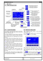
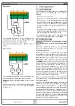
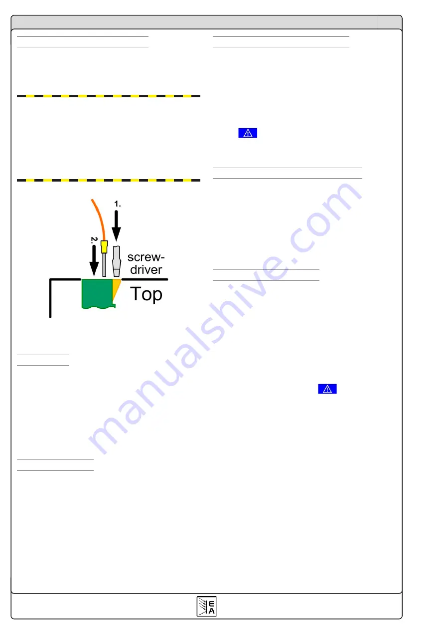
2.4 Analog interface connection
The 12 pole analog interface on the top side is of
type press & clamp. It is eligible for cable cross
sections of 0.1mm² (26 AWG) to 0.5mm² (20 AWG).
If possible, use cable end sleeves.
Attention! Never connect grounds of the ana-
logue interface to minus (negative) output of an
external control application (PLC, for example), if
that control application is already connected to
the negative power supply output (ground loop).
Load current might flow over the control leads
and damage the device! In order to avoid this a
fuse can be integrated in the „weak“ ground line.
Clamping procedure:
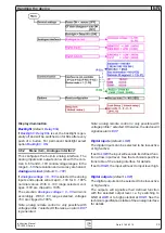
3. Functional description
3.1 General
The power supply is pre-configured 0 output voltage
and 100% output current.
The output voltage is supervised for adjustable
undervoltage thresholds.
The control panel is used to set conditions, set up the
device and to adjust output values. Alternatively, the
device can be remotely controlled via the internal,
analog interface or an option, digital interface card.
3.2 Remote sense
In order to compensate voltage drops along the load
leads, the device features remote sense inputs on
the front. Here the sensed voltage from the load
is connected with correct polarity. Remote sense
can compensate up to a certain level. Refer to the
technical specifications about that level.
When not using the sense inputs, they just remain
open. It is not required to bridge them to the output.
The cross section of the sense leads is non-critical.
3.3 Overvoltage protection (OVP)
All models feature an overvoltage protection circuit
which is set 110% of the nominal output voltage. In
case of an overvoltage condition, whether caused by
an internal defect or by external reasons, the power
output is switched off and the error is indicated by
the a status text „
OV
“ in the display and also by pin
„ERROR“ of the analog interface. The error indica-
tion remains in the display until acknowledged by
button
.
After the OV condition is gone, the output can be
switched on again.
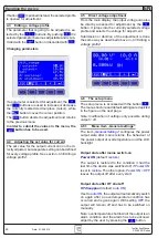
3.4 Output restoration after blackout
After a mains blackout (same as switching the in-
put voltage off by hand), the device will reconstruct
the last condition by restoring output state and set
values.
The output state restoration can be deactivated
in the setup menu by the parameter „
Power ON =
OFF
“, while „
Power ON = restore
“ will set the output
to the last condition before the blackout.
3.5 Overtemperature (OT)
All models also feature an internal temperature su-
pervision. In case of overheating, the power output
will be temporarily switched off until the device has
cooled down.
The state of the output after an OT error can be
configured in the setup. During an OT condition a
status text „
auto ON
“ indicates that the output will
be on after the OT condition is gone. This can be
deactivated by the parameter „
OT disappear = OFF
“.
The error indication remains in the display until it is
acknowledged by the button
.
The condition is indicated by the status text „
OT
“
in the display and by pin „ERROR“ of the analog
interface. The output state restoration can be de-
activated in the setup menu by the parameter „
OT
disappear = OFF
“.
About the device


