69
Instruction Manual
PSI 8000 3U Series
EN
Date: 05-03-2012
Operating the device
9. Digital interfaces
9.1 General
The power supply supports various interface cards for commu-
nication or analogue control. All cards, except Profibus card
IF-PB1, are galvanically isolated up to 2000V. The Profibus
card is isolated up to 1000V.
The digital interface cards IF-R1 (RS232), IF-C1(CAN) and IF-
U1(USB) use a uniform communication protocol. Up to 30 units
can be controlled from a PC at once with these cards.
The GPIB interface IF-G1 (IEEE 488) offers a SCPI command
structure for up to 15 units per bus. The analogue card IF-A1
is a galvanically isolated, analogue interface with configurable
in- and outputs.
The new Ethernet/LAN interface IF-E1 also provides SCPI
command set, as well as a browser surface. It features an
additional USB port which makes the device accessible like
with the IF-U1 card.
The Profibus card IF-PB1 is designed to be used on a field bus.
It offers DPV0 and DPV1 functionality at bus speeds of up to
12MBit/s, 125 Profibus addresses, 32 units per bus segment and
simple integration via a generic station description file (GSD).
An additional USB port includes complete functionality of a USB
interface card type IF-U1. It offers monitoring and controlling of
the unit with our custom, binary communication protocol. The
port only works alternatively to the Profibus port.
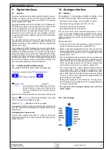
9.2 Configuring the interface cards
The interface cards have to be configured at least once.
This is done using the menu
Communication
.
+
Communi
Device node
Default:
1
= {1..30}
Up to 30 device nodes (addresses) can be as-
signed to devices, one per unit. A device node
must only be assigned once if multiple units are
controlled.
Except for the analogue interface it is necessary to set the unit’s
address (
Device node
) when using interface cards. Only
then the unit can be identified correctly.
Slot A:
{ IF-… }
depends on what is equipped
An equipped interface card is automatically recognized by the
unit. The menu selection displays the equipped card with its
product code.
Configuring the various cards
All cards have different parameters to configure. These are
explained in detail in the corresponding user instruction manual.
Please refer to it.
10. Analogue interface
10.1 General
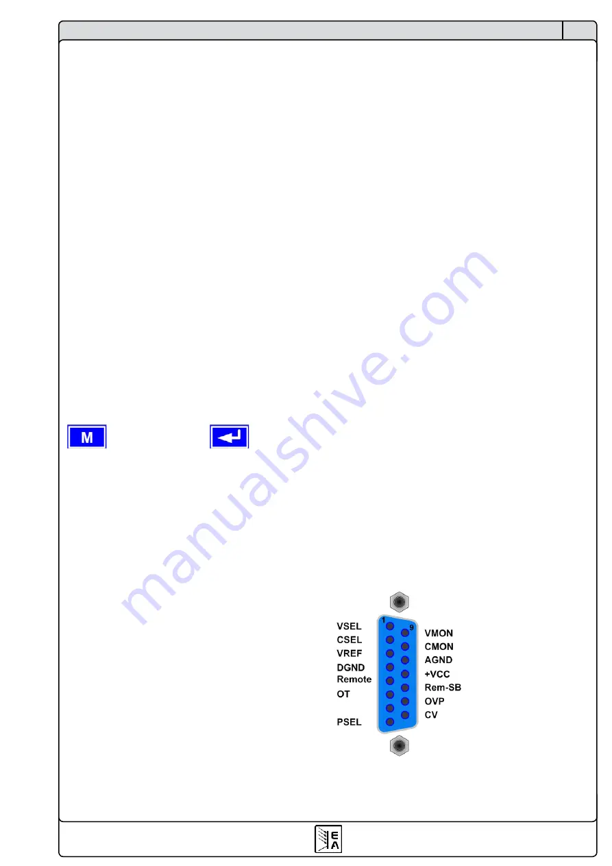
The integrated, 15 pole analogue interface is located on the
front and offers, amongst others, following possibilities:
• Remote control of output current, voltage and power
• Remote monitoring of status (OT, OVP, CC, CV)
• Remote monitoring of actual values
• Remotely switching the output on/off
The set value inputs can be operated with either 0...5V or
0...10V. The proper voltage range is selected in the device
setup. See section „7. Device configuration“. The reference
voltage at output pin 3 is tied to the chosen setting and will be
either 5V or 10V.
Usage instructions:
• Controlling the device with analogue voltages requires to
switch it to remote control with pin „REMOTE“ (5).
• Before connecting the application that is used to control the
power supply, make sure to wire all leads correctly and check
if the application is unable to put in voltages higher than
specified (max. 12V).
• The input REM-SB (remote standby, pin 13) overrides the
pushbutton
ON
. It means, the output can not be switched on
by the button if the pin defines the output state as „off“ So it
can be as emergency power off. This does not apply, if the
control location was set to
local
• The output VREF can be used to build set values for the set
value inputs VSEL, CSEL and PSEL. For example, if only
current control is required, pin VSEL and PSEL can be brid-
ged to VREF. CSEL is then either fed by an external voltage
(0...5V or 0...10V) or via a potentiometer between VREF and
ground. Also see next section.
• Putting in set values up to 10V while the 0...5V range is se-
lected will ignore any voltage above 5V (clipping) and keep
the output value at 100%.
• The grounds of the analogue interface are related to
minus output
.
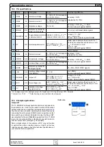
10.2 Pin overview
Содержание 09 230 430
Страница 2: ......
Страница 13: ...13 PSI 8000 3U 系列产品说明书 CN 日期 05 03 2012 关于产品 图 5 ...
Страница 38: ......
Страница 49: ...49 Instruction Manual PSI 8000 3U Series EN Date 05 03 2012 About the device Figure 5 ...

