56
© 2006, Elektro-Automatik GmbH & Co. KG
Irrtümer und Änderungen vorbehalten
EN
Instruction Manual
PSI 8000 3U Series
Date: 05-03-2012
Using the power supply
Indication
Alarm
Warning
Simple notification
Description
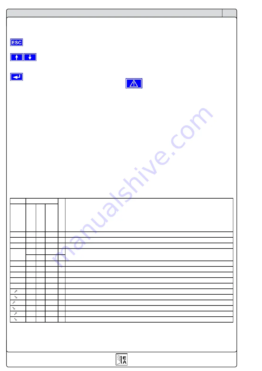
OV
Overvoltage at the power output
SYS
General system error
FCT
Function could not be saved and/or submitted
1)
2)
CAN
CAN bus transmission error
U>
def. def. def.
Overvoltage supervision threshold exceeded
U<
def. def. def.
Undervoltage supervision threshold exceeded
I>
def. def. def.
Overcurrent supervision threshold exceeded
I<
def. def. def.
Undercurrent supervision threshold exceeded
U
def. def. def.
Set-actual comparison error at a positive voltage transition
U
def. def. def.
Set-actual comparison error at a negative voltage transition
I
def. def. def.
Set-actual comparison error at a positive current transition
I
def. def. def.
Set-actual comparison error at a negative current transition
P
def. def. def.
Set-actual comparison error at a positive power transition
P
def. def. def.
Set-actual comparison error at a negative power transition
1)
OT disappear = OFF
2)
OT disappear = auto ON
def. = definable
Error type
Depending on
OT
Overtemperature error
6.12 Parameter pages
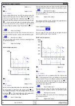
The parameter page is the lowest menu level. Here you can
change many different parameters in order to set up the device.
By pressing the
ESC
button the parameter page is left
to the next higher level and no parameters are accepted.
The
SELECT
keys are used to select a different
parameter. The selected parameter is then displayed invertedly
and can be changed with the left rotary knob.
The
RETURN
button submits the changed parameters,
which are accepted and stored and used. The parameter page
is also exited to the next higher level.
6.13 Alarms, warnings and signals
Alarms, warnings and simple notifications (here called „signals“)
can be acoustically signallised or optically in the display. The
pins „OT“ or „OVP“ of the built-in analogue interface or the
optional analogue interface card IF-A1 are also reporting over-
voltage or overtemperature. Also see section „7.4 Configuring
the control panel“.
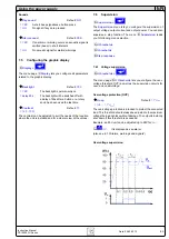
An alarm has a higher priority than a warning or signal. Up to
four alarms, warnings or signals can be displayed, which will
cycle in an interval of two seconds. If an alarm occurs, one
previous warning or signal will be suppressed if the total number
exceeds four.
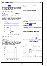
The output voltage, the output current and the difference bet-
ween actual and set value can be monitored.
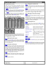
The table below gives an overview of the possible errors and
their meanings, as well as the selectable error types, as far as
these are configurable.
An
alarm
will shut down the output and has to be acknowledged
before the output can be switched on again (also see section
„6.14 Acknowledging alarms and warnings“).
A
warning
remains in display as long as it is not acknowledged
and can temporarily switch off the power output, if „
auto ON
“
has been activated for a particular error.
A
signal
is only displayed and only as long as the cause of the
error is persistent. If more than one signal is notified, they will
cycle in the display in a 2s interval.
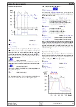
6.14 Acknowledging alarms and warnings
You can acknowledge alarms and warnings with the
QUIT
button.
If you acknowledge a warning with this button while it still per-
sists, it is turned into a signal and displayed furthermore. Else
it is deleted and not displayed anymore .
Содержание 09 230 430
Страница 2: ......
Страница 13: ...13 PSI 8000 3U 系列产品说明书 CN 日期 05 03 2012 关于产品 图 5 ...
Страница 38: ......
Страница 49: ...49 Instruction Manual PSI 8000 3U Series EN Date 05 03 2012 About the device Figure 5 ...

