background image


Data di emissione: 

Febbraio, 2019

              Revisione: 

6                              

   Pag. :

 13/28


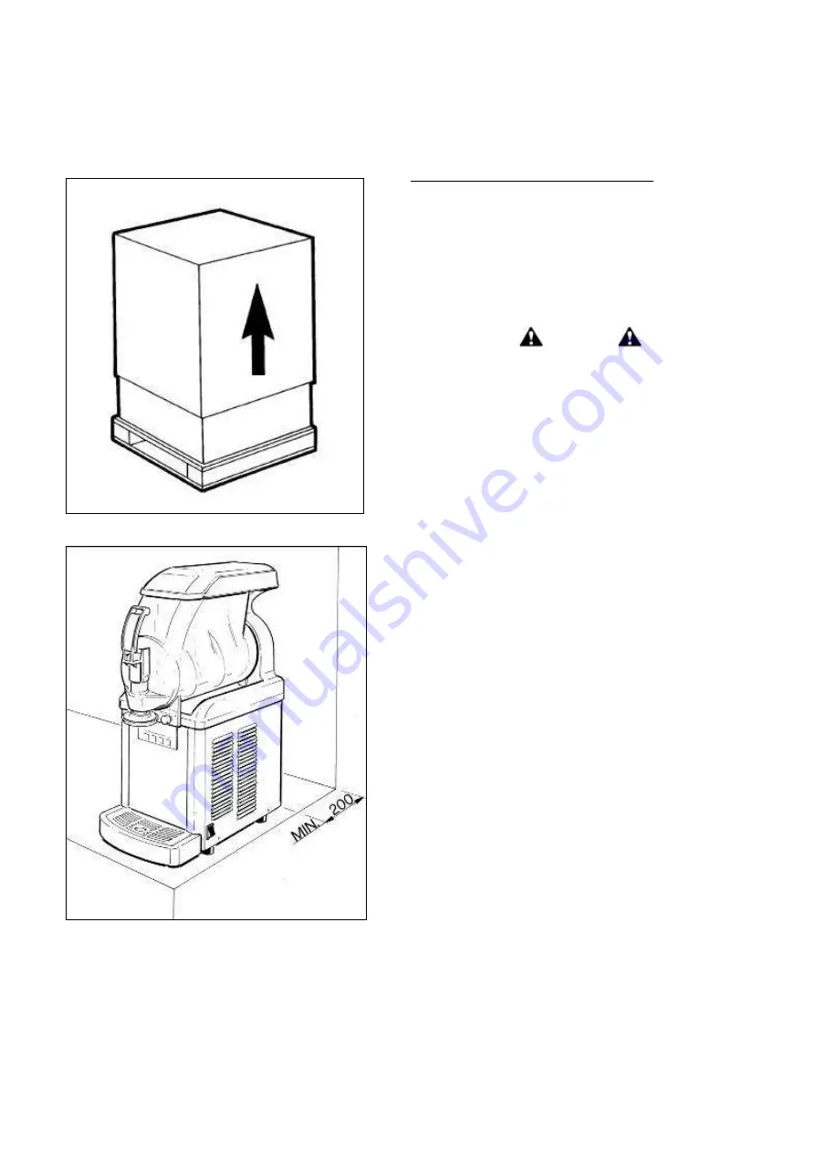
Fig. 19


Fig. 20


6.  POSITIONING 


FOR MAINTENANCE WORKER ONLY 

The  installation  and  subsequent  servicing 
operations  must  be  carried  out  by  skilled 
members who have been trained to use the 
device 

and 

in 

compliance 

with 

the 

regulations in force. 


a)


Remove the packing (fig.19) and preserve it 
in order to reuse for winter storage. 


 Caution 


All the parts of the packaging must be kept 

beyond the range of children, as they might 

represent a potential safety/health risk. 


b)


Make  sure  the  machine  is  in  perfect 
condition. 


b)  Rest  the  machine  on  a  sturdy,  flat  surface 
making  sure  it  is  well  ventilated  by  leaving  a 
gap of 20 cm around it and do not install it near 
heat  sources  (fig.20); 

we  recommend  you  to 

maintain  a  room  temperature  between  24 
and 32°C. 


c)  Check  that  the  power  mains  voltage  meets 
the 

specifications 

on 

the 

equipment 

identification plate and that the output available 
meets the device’s power requirements. 
Fit the plug into an earthed socket, removing all 
multiple adaptors. 


FOR FURTHER PRECAUTIONS, READ THE 

SECTION “CONNECTION TO THE ELECTRICITY 

MAINS” CAREFULLY.


d)  The  installation  must  be  carried  out  in 
accordance with the manufacturer’s instructions. 
Failure  to  comply  with  the  positioning  and 
installation 

instructions 

may 

impair 

the 

machine’s operation. 


Important 

You are legally required to provide a suitable 

grounding system for the equipment. 

Before carrying out any cleaning and/or special 

maintenance on the device, make sure it is 

disconnected from the mains by unplugging it. 

In the event of a breakdown or malfunctioning, 

switch off the device and remove the plug. 

Содержание GT1 Push

Страница 1: ...Data di emissione Febbraio 2019 Revisione 6 Pag 1 28 GT1 e GT2 Push Operator s manual ...

Страница 2: ...ents has been drafted by following the dispositions 2006 42 CE and reports the technical information that are necessary to correctly run all the procedures under safety conditions must be carefully kept protected by a transparent watertight wrapping in order to avoid any damage and must go with the machine during its life including potential changes of ownership In case of loss or damage it s poss...

Страница 3: ... LIFTING TIPS 11 5 TECHNICAL SPECIFICATIONS 12 6 POSITIONING 13 7 CONNECTION TO THE POWER SUPPLY MAINS 14 8 START UP PROCEDURES 15 9 OPERATING INSTRUCTIONS 17 10 SPECIAL MAINTENTANCE 18 Condenser cleaning 18 Control and replacement of seals 19 Winter storage 19 11 SOFT SERVE ICE CREAM INFORMATION 20 12 DISCLAIMER 20 13 TROUBLESHOOTING GUIDE 21 14 WIRING DIAGRAM 22 ...

Страница 4: ...shall not play with the appliance Cleaning and user maintenance shall not be made by children without supervision This equipment is not suitable for outdoor use This machine is not suitable for installation in locations where water jets are used and it must not be cleaned by a water jet This appliance must be installed in places where it can be checked by qualified personnel Do not store explosive...

Страница 5: ...fore start up to ensure the best possible cleanliness Caution Electric shock hazard Do not splash water on switches or allow water to flow onto electrical components inside the machine Caution To prevent bacteria growth use only sanitizers approved for plastic and rubber objects failure to do so could create a health hazard Note it is responsibility of the operator to be aware of and conform to th...

Страница 6: ...terms of time and modes of conservation After unlocking the main cover with its key fig 1 remove the main cover and the secondary one under it fig 2 Pour lukewarm water into the bowl fig 3 and after re positioning the main cover make the scraper auger rotating for some minutes all LED switched off NOTE GT is equipped with a very efficient safety mechanism activated when the cover is lifted designe...

Страница 7: ...itize your hands and forearms Unscrew the bowl knobs fig 5 Remove the accessory to give a star peculiar shape to the dispensed product fig 6 Simultaneously press the two securing tabs and lift the tap to extract it from its seat see fig 7 Disassemble the tap by keeping the body pressed down and slipping the lever from its seat fig 7 Caution To prevent bacteria growth remove all o rings when cleani...

Страница 8: ...e bowl and the other components CAUTION Never perform these washing operation with a dish washing machine failure to do so could seriously damage the unit s parts Rinse well and then place all the components in the sanitizer solution for proper sanitizing the parts must remain fully plunged for 15 minutes or as recommended by the sanitizer manufacturer After respecting the correct sanitizing perio...

Страница 9: ...ashed and sanitized before assembling Persons assembling the machine must first wash and sanitize their hands and forearms with an approved sanitizer Spread Vaseline on the bell shaped seal internal surface before reassembling it fig 12 Reassemble the rear gasket and the bell shaped one respecting the correct direction as indicated in figure 13 Reassemble the mixing unit making sure that the front...

Страница 10: ...e fig 16 Fix the bowl by reinsert the knobs fig 17 IMPORTANT Do not over tighten the bowl knobs Excessive force could damage the thread and or the bowl itself Re insert the tap fig 18 spreading Vaseline on the o rings to facilitate sliding the tap in its seat until completely inserted Warning If the tap does not perfectly slide into position the sealing hold will be endangered Reassemble the acces...

Страница 11: ...p tray 3 TRANPORT TIPS To prevent the oil held in the hermetic compressor running into the cooling circuit the device must be carried stored and handled in the upright position following the direction instructions on the packing If the device is accidentally or intentionally for transportation reasons kept in any other position it must be set again in the correct position at least twenty minutes b...

Страница 12: ...s any technical problem can be settled with slight interventions please see the troubleshooting guide at the end of this manual we therefore recommend you to carefully read this handbook before contacting the manufacturer or service centre Disposal Caution All the parts of the packaging must be kept beyond the range of children as they might represent a potential safety health risk Important In re...

Страница 13: ...es fig 20 we recommend you to maintain a room temperature between 24 and 32 C c Check that the power mains voltage meets the specifications on the equipment identification plate and that the output available meets the device s power requirements Fit the plug into an earthed socket removing all multiple adaptors FOR FURTHER PRECAUTIONS READ THE SECTION CONNECTION TO THE ELECTRICITY MAINS CAREFULLY ...

Страница 14: ...erify electrical specifications on the data plate of each machine Data plate specifications always replace the information of this manual For a safe and correct installation it is essential to provide a suitable socket controlled by a thermal cut out switch whose contacts are at least 3 mm apart in accordance with the current national safety regulations see fig 21 Never use extensions or multiple ...

Страница 15: ...n during its freezing so it is very important to control it in order to avoid to go over the bowl maximum level please see the chapter about the overrun calculation Pour the mix obtained into the bowl see fig 23 Restore the secondary cover and then the main one making sure to fix it with the security key Note GT1 and GT2 are equipped with a very efficient safety mechanism designed to protect the o...

Страница 16: ...nction using the button with waves on it The other way round if you need to switch from DEFROST mode to FREEZING one it s necessary to disable the defrost function pressing the waves button and enable the freezing function pressing the snowflake one NOTE when the first and last LED of the consistency scale winkle at the same time it means that the product inside the bowl is below the minimum level...

Страница 17: ...consistency with the e buttons fig 27 DEFROST This mode once activated by the waves button reduces the machine energy consumption the refrigerating system will automatically cycle to maintain temperature below 2 C fig 9 Use this position when product will not be requested for hours Important Do not use FROZEN or DEFROST position with water or sanitizer in the bowl the machine will be damaged NOTE ...

Страница 18: ...ce the condenser must be well cleaned every month How to reach it Switch off the power supply and disconnect the power cable GT1 machine remove the rear panel by unscrewing the two bolts fastening it fig 28 GT2 machine remove the left side panel by unscrewing the two bolts fastening it fig 29 Using a dust exhauster remove the dust that has collected between the condenser fins fig 30 IMPORTANT Neve...

Страница 19: ...el of maintenance This part should be lubricated during the re assembly after every cleaning with Vaseline EVAPORATOR HARD SEAL Replace every 9 to12 months according to the conditions of use and level of maintenance Winter storage To protect the unit during seasonal shutdown it s important to properly store the machine using the following procedures Disconnect all power to the freezer Disassemble ...

Страница 20: ...ht of frozen product divided by the frozen weight Multiply by 100 Example Weight of half litre of mix 530g Weight of half litre of frozen product 380g Difference 150g 150 380 0 4 0 4x100 40 overrun 12 DISCLAIMER The manufacturer declines all responsibility for any damage that directly or indirectly might be brought on to people things animals as a consequence of failure to comply with all instruct...

Страница 21: ...ts and and correct those incomplete Replace the switch Replace the control board Replace the DC drive Replace the gear motor The bowl is leaking One of the bowl seal is not in place Replace or reposition the seal The dispensing valve is leaking The dispensing valve has been incompletely or incorrectly replaced in its position The free movement of the valve is impeded Dispensing valve o rings are d...

Страница 22: ...Data di emissione Febbraio 2019 Revisione 6 Pag 22 28 14 WIRING DIAGRAM ...

Страница 23: ...Data di emissione Febbraio 2019 Revisione 6 Pag 23 28 ...

Страница 24: ...Data di emissione Febbraio 2019 Revisione 6 Pag 24 28 ...

Страница 25: ...Data di emissione Febbraio 2019 Revisione 6 Pag 25 28 ...

Страница 26: ...Data di emissione Febbraio 2019 Revisione 6 Pag 26 28 ...

Страница 27: ...Data di emissione Febbraio 2019 Revisione 6 Pag 27 28 ...

Страница 28: ...Data di emissione Febbraio 2019 Revisione 6 Pag 28 28 Electrolux Professional SPA Viale Treviso 15 33170 Pordenone www electrolux com professional ...
Отзывы: