Electrolux AOS061ECR2 Скачать руководство пользователя страница 4

 30

GB

5938 033 01

3.1   INSTALLING THE POWER SUPPLY CABLE

To access the power supply cable connection terminal board,
proceed as follows:

Model 6 - 10 - 20 GN

• Remove the left side panel.
• Connect the power supply cable to the terminal board  accord-
ing to the instructions given in the wiring diagram and fasten the
power supply cable by means of the cable clamp.

The manufacturer declines all responsibility if the applicable
safety regulations are disregarded.

4.   WATER MAINS CONNECTION

(Refer to the installation diagrams at the beginning of this book-
let).

When connecting the appliance to the water system with
flexible tubes they must be new and not used.

The appliance is fitted with two separate water inlets ("B" and "N").
The water lines supplying both inlets must be fitted with a
mechanical filter and shut-off cock.
Before fitting the filters allow the water to flow out for sufficient time
to flush any solid particles from the piping.

Pressure

 between 

150 and 450 kPa (1.5-4.5 bar).

WATER INLET “N”

Attention 

 (water inlet N)

If the supply pipes provided with the appliance are not long
enough for installation, use longer ones with 

int. diameter 


at

least ø 20 mm

 and free of elbow unions.

Note:

 To check correct water installation, make sure the rotating wash
arm (CLEANING SYSTEM) does not turn below 100 rpm (120
max).

4.1   WATER SUPPLY CHARACTERISTICS

The appliance must be supplied with 

drinking water 

having

specific characteristics given in this section.
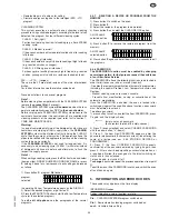
HARDNESS FILTER

° f

p p m

° d H

W a t e r  

i n l e t

A p p l .

H a r d n e s s

A   ^

0 , 5   -   5

5   -   5 0

0 , 2 8   -   2 , 8

B   ^

0 , 5   -   5

5   -   5 0

0 , 2 8   -   2 , 8

C   ^

m a x   5

m a x   5 0

m a x   2 , 8

A   ^

m a x   5

m a x   5 0

m a x   2 , 8

B   ^

m a x   4 0

m a x   4 0 0

m a x   2 2

C   ^

m a x   5

m a x   5 0

m a x   2 , 8

N

B

^ OPERATING LEVEL (C = Convect, Convection).

The 

hardness values

 given in the table are for reducing scaling

inside the steam generator and possible cooking compartment
washing system.
If the available water does not have these hardness characteristics
a water softener must be installed.
Therefore the Automatic Water Softener with automatic
regeneration for installing on the inlet line, can be requested as
an accessory; it has a Resin Sterilizer kit (also by request).

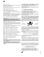
HARDNESS AND CHLORIDE FILTERS

The 

chloride concentration (Cl-) (ppm - mg/l) 

values with 

pH

(>7) and 

Conductivity (µS/cm) 

(measured at 20°C) must be

such as to not damage the steel structures inside the oven (only
water inlet B).
Therefore the characteristics of the available water must be
identified in the graph given at the end of this handbook (page
251), if necessary installing at the inlet the type of filter indicated
in the relevant area of the values.

II.   INSTRUCTIONS FOR INSTALLATION

Important

: The oven outer panels must be removed to 

perform the operations described in this chapter

Since the 

appliance must be switched on to make certain 
adjustments, exercise the utmost care when working in the 
vicinity of live electrical parts.


1.   PLACE OF INSTALLATION

• The appliance must only be installed in adequately ventilated
premises.

1.1 REFERENCE STANDARDS

Install the appliance according to the prescriptions of current

safety standards.

2.  POSITIONING

• Unpack the appliance and carefully remove the protective film
from the outer panels to avoid leaving any trace of adhesive. Use
a suitable solvent to remove any adhesive residues.

• Dispose of the packaging as instructed in the chapter on
"Safeguarding the environment"

• Refer to the installation diagrams at the beginning of this
booklet for the space requirements and connection dimensions
of the appliance.
• Clearance of approximately 

50 cm

 must be left between the

appliance’s left side panel and adjacent structures in order to
provide space for maintenance operations when needed; the
right side panel and the rear panel of the appliance must be at
least 

10 cm

 from adjacent structures.

• Place the appliance in the required position and adjust the
height of the work surface using the adjustable feet.
• The appliance is not suitable for built-in installation.

Important

Make sure steam from the oven’s drain or adjacent 
appliances does not enter the aeration vents under the 
appliance, designed to cool internal components 
located at the bottom of the appliance. 


3.   ELECTRICAL CONNECTION

The appliance must be connected to the mains power supply
in compliance with current regulations.

• Before connecting the appliance to the mains supply, make

sure that the voltage and frequency shown on the appliance
identification dataplate correspond with those of the power
supply.

• The appliance must be permanently connected to the mains

power supply with an H05 RN-F type cable. The power supply
cable must be protected by a metal or rigid plastic conduit. If the
appliance is connected by way of an existing lead, do not insert
the cable conduit into the appliance and make particularly sure
that the conduit has no sharp edges.

• A safety cutout switch of suitable capacity with a contact

breaking distance of at least 3 mm must be fitted upstream of
the appliance.
The cutout switch must be installed near the appliance in the
permanent electrical system of the premises.

•   Appliance maximum leakage current is 1 mA/kW
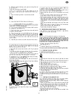
• The appliance must be suitably earthed. The earthing conductor

must therefore be connected to the terminal marked 

G

on the

connection terminal board. The appliance must also be
connected to an earth bonding system.
This connection is made using the stop screw marked 

E

located on the outside of the appliance near the power cable
inlet.
The bonding wire must have a minimum cross-section of
10 mm

2

.

Содержание AOS061ECR2

Страница 1: ... 3 1 Installing the power supply cable 30 4 Water mains connection 30 4 1 Water supply characteristics 30 4 2 Water drain system 31 5 Safety devices 31 6 Operation check 31 7 Servicing 32 8 Troubleshooting 32 9 Layout of main components 32 III INSTRUCTIONS FOR USE 33 1 Opening the oven door 33 1 1 6 and 10 grid models 33 1 2 20 grid models 33 2 Closing the oven door 33 2 1 6 and 10 grid models 33 ...

Страница 2: ...000 269010 239000 239010 649000 649070 269020 239020 269002 269012 239002 239012 649002 649072 269022 239022 269003 239003 649003 269004 269014 239004 239014 649004 649074 269024 239024 269005 239005 649005 400 3 N 400 3 N 230 3 230 3 200 3 400 3 N 400 3 N 230 3 230 3 200 3 400 3 N 400 3 N 200 3 400 3 N 400 3 N 230 3 230 3 400 3 N 400 3 N 50 60 50 60 50 60 50 61 50 60 50 60 50 60 50 60 50 60 50 60...

Страница 3: ... friendly Theymaybestoredatnoriskorburntatanauthorisedincineration plant Plastic materials suitable for recycling are marked with the following symbols polyethylene external wrapping film instructions PE booklet bag and gas injectors bag polypropylene top packaging panels and straps pp expanded polystyrene protective surround elements PS 4 2 USE Theappliancehasbeendesignedandperfectedunderlaborato...

Страница 4: ...nt The oven outer panels must be removed to perform the operations described in this chapter Since the appliance must be switched on to make certain adjustments exercise the utmost care when working in the vicinity of live electrical parts 1 PLACE OF INSTALLATION Theappliancemustonlybeinstalledinadequatelyventilated premises 1 1REFERENCESTANDARDS Install the appliance according to the prescription...

Страница 5: ...or routed to a floor gulley with grat ing The flexible drainage hose or rigid pipe can be directed to the side or rear of the appliance if the oven is not positioned against a wall this line must not be directed towards the front of the appliance to prevent interference with roll in grid racks The drain age pipe internal diameter must be no smaller than the oven drain outlet 1 1 4 no longer than 1...

Страница 6: ...mal use of the appliance Oven chamber heating not started or inefficient Possible causes Oven chamber temperature limit switch tripped Damaged heating elements Damaged heating element contactor coil Damaged thermostat probe showing error EPt1 Damaged controller Fuse F2 blown see circuit diagram Steam production not started or inefficient Possible causes Damaged heating elements Damaged heating ele...

Страница 7: ...e the oven chamber particularly during cooking cycles with humidification Donotcookwithflammableliquidssuchasalcoholicspirits The maximum height at which the trays are placed in the oven must not exceed 1 6 m This applies if installed according to the instructions and using original accessories except for stacked ovens In case of stacked ovens or in any other case when the above distance is exceed...

Страница 8: ...igital thermometer thermostat to control product core tem perature 3 4 SPECIAL COOKING MODES Utilities Functions useful for the type of cooking to be executed Pause phase set a time in this mode to delay the start of cooking programs or to set a pause interval between two cooking cycles e g for dough proving Regeneration cycle gives ideal humidity conditions for rapid heating of products to be reg...

Страница 9: ...o water Make sure the oven water supply is working Cooking parameter adjustment allows adjustment of cooking values humidity temperature and time Automatic sequence phases to execute a 2 phase cooking cycle switching from one phase to the other automatically LEVEL B e C ONLY 3 5 ADDITIONALFUNCTIONS Set of controls for management of the programs library control keys to store edit or delete cooking ...

Страница 10: ...iler ready LED off 4 1 1 SWITCHING THE OVEN OFF To switch the oven off press button O of this switch 4 2 SELECTING THE CONTROLS MANUAL or AUTOMATIC The control panel is divided in two parts one for MANUAL controls and the other additional section for AUTOMATIC controls MANUAL controls AUTOMATIC controls level B e C level A Use one of the two control modes according to your cooking needs in the lev...

Страница 11: ...product core reaches the set temperature Important The temperature probe is a precision instrument and must be handled with care Avoid knocks do not apply excessive force when inserting the probe and do not pull on the lead take care particularly when using roll in racks The guarantee does not cover damage to the core temperature probe caused by improper use 1 Switch on the oven Remove the product...

Страница 12: ... displays will show HU humidity inside the compartment TS automatic compartment preheating PrEH To skip preheat ing press the START button again TM time remaining for end of cooking PRB core probe tem perature Note In TIMED cooking during preheating the set cooking time remains unchanged COUNT DOWN not activated At the end of preheating the message LOAD appears on the display TS open the oven door...

Страница 13: ...N inactive phase at the same time the cooking modes button LEDs start flashing again to request a new setting for phase 2 5 Select phase 2 cooking mode phase 2 oven chamber temperature time or core probe temperature relative to phase 2 6 The two phase cooking cycle has now been set Place the product to be cooked in the oven and press the START STOP button to start the cooking cycle The cooking cyc...

Страница 14: ...core probe 70 C Phase 2 mixed cycle 220 C time 40 minutes Phase 3 air convection cycle 250 C time 15 minutes and so on up to a maximum of 7 phases During the cooking cycle the oven advances from one phase to the next one automatically until the cooking program is completed and then stops automatically as soon as the last phase has been terminated To set a multiple phase cooking program proceed as ...

Страница 15: ... to remind the user that this function is active 4 4 3 EDITING THE SET PARAMETERS With the cooking cycle blocked started or stored use the relative commands to edit the following parameters 1 cooking mode 2 cooking temperature TS 3 cooking time TM 4 probe temperature PRB in alternative to cooking time Note When you edit the parameters of a STORED cooking program during a cooking cycle an asterisk ...

Страница 16: ...e of the desired recipe from those beginning with the letter G desired recipe 1 5 G OO S E selected P M E N U 4 4 6 USING PRESET PROGRAMS Undeletable preset programs provide several standard service functions The oven is supplied with the following preset programs LOW TEMPERATURE COOKING EFS LTC Cooking at low temperature is a specific cooking procedure especiallyforbeef e g primerib beeffillet to...

Страница 17: ...PLAY 2 Select the desired program or go to step 3 3 PresstheSTART STOPbuttontostarttheA0LowTemperature cycle or the selected program To exit edit skip phase see the paragraphs of the normal programs 4 4 7 DELETING A RECIPE OR PROGRAM FROM THE MEMORY 1 Press button I to switch on the oven 2 Press button P 3 Select the recipe or the program to be deleted 4 Press button P and select the CLEAR RECIPE ...

Страница 18: ...personnel trained and authorised by the manufacturer 7 CARE AND MAINTENANCE At the end of each day clean the oven interior with an oven cleaner following the product supplier s directions Do not wash the appliance with water jets Do not clean steel surfaces with products containing chlorine bleach hydrochloric acid etc even diluted Do not use corrosive substances e g muriatic acid to clean the flo...

Страница 19: ...shes or scrapers since they may leave ferrous particles which will promote rusting on the steel surfaces If the appliance is not to be used for long periods proceed as follows Disconnect the electrical power supply and turn off the water cocks Using a cloth soaked in vaseline oil vigorously rub the stainless steel surfaces to apply a light protective film Periodically air the place of storage 7 1 ...

Страница 20: ...ve all traces of old silicone from the channel apply a bead of silicone sealant in point 1 along the internal frame of the seal seating channel insert the new seal pressing it home along the entire length of the channel 4 7 3 SPECIAL CLEANING INSTRUCTIONS Cleaning and checking the drain system Periodically clean the drain pipe and check for obstructions that may prevent the water from draining Cle...

Отзывы: