Operating and installation
instructions
(Translation of the original operating instructions)
DOC no. 87.8031.01 - EN
Edition 4 (01-2020)
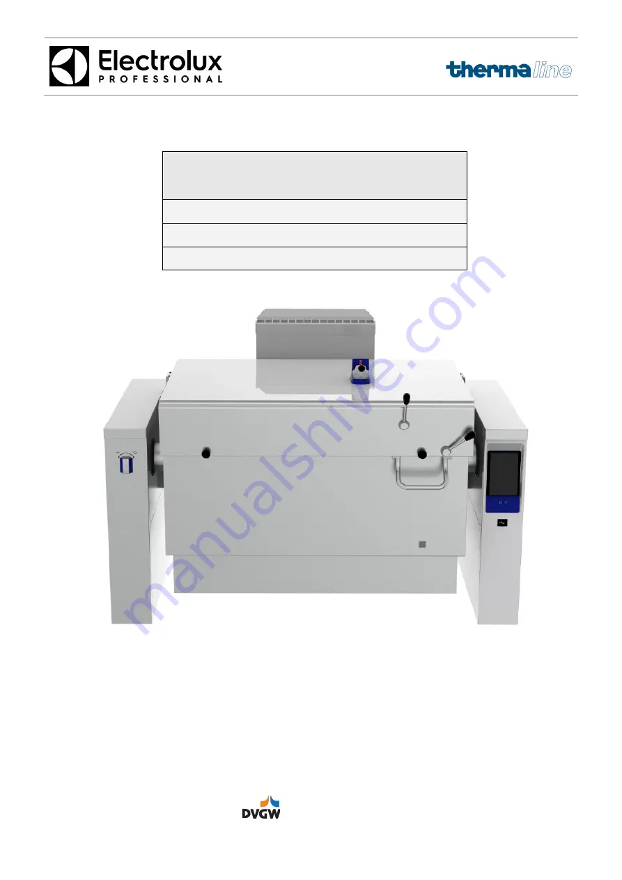
Pro Thermetic
TILTING PRESSURE BRAISING PAN
PUET MODEL
Gas powered
│
PUET-G
A
BC
Страница 1: ...rating and installation instructions Translation of the original operating instructions DOC no 87 8031 01 EN Edition 4 01 2020 Pro Thermetic TILTING PRESSURE BRAISING PAN PUET MODEL Gas powered PUET G A BC ...
Страница 2: ...ctions 11 1 7 4 Moving the appliance and setting down the load 11 1 7 5 Storage 11 2 APPLIANCE FUNCTIONS AND EQUIPMENT 12 2 1 OVERVIEW 12 2 2 APPLIANCE FUNCTION 12 2 3 DESIGN AND SET UP 12 2 3 1 Brief description of the most important working parts 13 2 4 EXTENSION OPTIONS 13 2 5 TESTS CERTIFICATES 13 3 TECHNICAL SPECIFICATIONS 14 3 1 VALIDITY AND IDENTIFICATION 14 3 2 APPLIANCE MODEL CODING 14 3 ...
Страница 3: ...36 8 2 OPERATING THE MAIN FUNCTIONS 36 8 2 1 Main selection menu 36 8 2 2 Default settings 36 8 2 3 Manual 37 8 2 4 Phase 37 8 2 5 Temperature selection in Celsius 37 8 2 6 Temperature selection via power levels 37 8 2 7 Selecting cooking time entering time and continuous cooking 38 8 2 8 Selecting cooking time via core temperature sensor in Celsius 38 8 2 9 Delayed start 38 8 2 10 Pressure cookin...
Страница 4: ...ble place where they can be consulted at any time in case of doubt or when required Should you have any doubts or uncertainties concerning the use of the machine or cooking appliance after reading the operating and installation instructions please contact Electrolux Professional or your closest customer service centre who will gladly assist you to optimise the performance of the appliance It must ...
Страница 5: ... The 8 digit series number on the ID plate is compiled as follows Until 11 2013 Y WW XXXXX Y is the last figure of the year of manufacture WW stands for the week of manufacture XXXXX is the consecutive serial number From 11 2013 3 38 1 0003 Y WW Z XXXX Y Fourth digit of the year in numbers 2013 WW Calendar week 38 Z Third digit of the year in numbers 2013 XXXXX 3 Appliance with this PNC produced i...
Страница 6: ... must be stored together with them Electrolux Professional shall bear no responsibility for any inaccuracies in the operating instructions and installation instructions that are due to printing or translation errors 1 3 1 Storing the operating instructions The operating instructions must be kept intact for the whole life cycle of the appliance up until it is disposed of The operating instructions ...
Страница 7: ...re Do not place any objects on the lid or on the heating zones during use Do not heat up covered containers due to the risk of explosion and injury The use of hazardous substances such as highly concentrated vinegar essence citric acid limescale cleaners or flammable substances on our cookers is strictly forbidden Overheated oil can self ignite Never put water on burning oil but put out the flames...
Страница 8: ...aration The reason the anti rust stainless steel can resist corrosion is a passive layer which builds up when oxygen hits the metal surface There is sufficient oxygen in the air to do this If this passive layer is damaged by mechanical effects or damaged chemically and the passive layer is prevented from regenerating itself lack of oxygen even rust free stainless steel may corrode It is possible t...
Страница 9: ... parts such as fans inside the appliance There is a high risk of injury Take extreme care The appliance must be blocked via external valves prior to performing maintenance work on pressure parts Repairs and service on the appliances must be carried out when heating elements have cooled down Do not use any inflammable liquids to clean the appliance In the event of a persistent defect that prevents ...
Страница 10: ...g appli ances must be thoroughly rinsed with water and rubbed dry The surfaces of our cooking appliances are made of rust resistance chromium nickel steel They must be washed with a hot mild cleaning agent and rubbed dry They must not be cleaned with wire brushes wire wool copper cloths sand based products or similar because using such agents damages the surfaces and creates conditions for corrosi...
Страница 11: ...tenings and that the load cannot fall from the vehicle as a result Standing under hanging loads during loading and unloading is prohibited Unauthorised persons are prohibited from accessing the work area Prepare a suitable location with an even floor for the unloading and storage of the appliances 1 7 3 Handling instructions To ensure that that appliances are lifted safely the following precaution...
Страница 12: ... interface The main functions include Programmable cooking processes Loading and storing all parameters for individual and multi phase cooking processes on a USB disc Large clear simultaneous display of actual and target values Real time clock Programmable timer for individual and user specific cooking start A generous selection of nine power levels will help your individual cooking requirements m...
Страница 13: ...dard appliances at the factory Please contact the factory first of all to ensure that they are available and that extension is possible Below there is a round up of optional extras Mixer tap Automatic water filling device Cold water hot and cold water Spray gun Main switch power supply Energy optimisation EO Potential free contact PC Measuring stick Suspension frame for GN containers Perforated GN...
Страница 14: ...logue 87 8031 02 in the customer services centre Service manual 87 8031 03 in customer services centre Parameter programming 87 8005 01 in the customer services centre Electrical wiring diagram Supplied with the appliance and published in the service manual 3 4 TYPE OF INSTALLATION The tilting pressure cooker is optionally available as freestanding as an island on feet chromium steel or concrete b...
Страница 15: ...ll level mark 90 170 Gas quantities 1013 mbar 15 C at sea level Natural gas H m3 h 1 86 3 00 Natural gas L m3 h 2 17 3 48 Propane kg h 1 40 2 25 Butane kg h 1 42 2 29 3 6 2 Performance data Water heating times as per DIN18855 1 2005 07 PUET06 PUET09 PUET11 PUET17 Water heating times Net capacity in litres max fill quantity 67 94 104 145 Heating from 20 90 C Time required in minutes empty pan 10 Fi...
Страница 16: ... instructions Pro Thermetic Tilting pressure braising pan PUET G EN 01 2020 87 8031 01 16 4 INSTALLATION ASSEMBLY 4 1 DIMENSION DRAWINGS FOR FLOOR AND WALL INSTALLATION 4 1 1 Appliances installed on the floor and against a wall ...
Страница 17: ...Operating and installation instructions Pro Thermetic Tilting pressure braising pan PUET G EN 01 2020 87 8031 01 17 4 1 2 Wall mounted appliances ...
Страница 18: ... on the floor and against a wall EI Electrical connection G Gas connection Customer s supply pipe Natural gas town gas 1 DN25 Liquid gas 3 4 DN20 HWI Hot water inlet G 1 2 NW15 CWI Cold water inlet G 1 2 NW15 D Condensate outlet BF Floor attachment points Info Steel or wall plinth standard 100mm for appliance height 800mm Steel or wall plinth hygienic 200mm for appliance height 700mm ...
Страница 19: ... PUET G EN 01 2020 87 8031 01 19 4 2 2 Wall mounted appliances EI Electrical connection G Gas connection Customer s supply pipe Natural gas town gas 1 DN25 Liquid gas 3 4 DN20 HWI Hot water inlet G 1 2 NW15 CWI Cold water inlet G 1 2 NW15 D Condensate outlet BW Wall attachment points ...
Страница 20: ...are usually cemented into the floor with an outlet Installation Island freestanding Insel freistehend Installation Wallstanding An Wand stehend 4 4 INSTALLING THE APPLIANCE The appliance should always be installed in its intended location according to the relevant diagrams The appliance should be connected to fixed cables Individual or groups of appliances can be fitted freestanding as an island s...
Страница 21: ... panel cover A B Lift off the panel covers A B 4 5 3 Removing the service cover V Remove the service covers V by removing the screws S3 4 5 4 Removing the side panels S First remove the control panels F and panel covers A B Remove the side panels S by removing the four M4 nuts M2 located on the inside of the panel 4 5 5 Removing protective coverings SA The installation connections e g for electric...
Страница 22: ...ial Put the appliance down carefully and move it into the desired final position align it horizontally and fix Remove panel cover A B and the service covers S3 see 4 5 ACCESS TO THE INSIDE OF THE APPLIANCE Electrical and water connections as per the description see 4 8 ELECTRICAL CONNECTION see 4 9 MIXER TAP When the appliance has been installed successfully re attach the panel covers A B and the ...
Страница 23: ...desired installation position The pallet truck H is to be driven as close as possible to the appliance A H R Carefully tilt the appliance onto the stable base A on the pallet truck H so that it is lying horizontally and move it into the correct position Remove the transport pallet R and dispose of it professionally together with the packaging material R A H Remove panel cover A B as well as protec...
Страница 24: ...y align all supporting brackets E in a row Level all of the set screws S in the supporting brackets E Carefully insert the equipment into the wall anchor threaded bolts level using a spirit level WA fasten using washer U and nuts M and fit the lock nut KM W Wall anchor with threaded bolts WM Wall anchor nut M Nut KM Lock nut E Supporting bracket S Adjustment screws with lock nut U U washer L Ruler...
Страница 25: ... 2 2 Meaning of the identification plate fields The following must be checked before connecting the appliance to the local gas connec tion whether the appliance is set up for the type of gas available To do this you must find out whether the information on the identification plate or an additional plate associated with it matches the existing type of gas If for any reason at all the conditions reg...
Страница 26: ...pipe MS with the screw socket GM the bracket FW the gas valve screws VG the gas valve GV and the screws VR are connected as in the figure below to the G 1 gas pipe G sticking out of the floor BO and a cut off valve AV is fitted After connection the service cover V and the panel front F must be refitted 4 8 3 Wall mounted appliances The gas is connected in accordance with the valid installation pla...
Страница 27: ...ines in force DVGW work sheet G 631 4 8 7 Testing the connection pressure Referring to the identification plate check whether the appliance is suitable for the type of gas If not see 4 8 1 General information and important instructions The gas connection pressure must be measured with a liquid U pipe pressure gauge resolution at least 1 mm water column This must be done as follows Turn off the cus...
Страница 28: ... adjust ment screw 4 8 9 Burner spacing The required appliance specific burner spacing is preset at the factory If the burner is replaced or removed the settings and values must be adjusted in accordance with Settings table in the Appendix F Pan BS Burner system D1 Burner space behind D2 Burner space in front Appliance model D1 D2 PUET06 tba tba PUET17 tba tba 4 8 10 Thermal load If a check of the...
Страница 29: ...e appliances must fulfil the following conditions Max voltage fluctuations 10 Max frequency fluctuations 1 continuous or 2 short term The harmonic distortion the phase imbalance of the three phase supply the voltage pulses power failures voltage leakage and other electrical characteristics must fulfil the requirements of clause 4 3 2 of EN 60204 1 IEC 60204 1 IMPORTANT The appliances must be secur...
Страница 30: ...ernal monitoring of the appliance are available as options Connect as shown in the electrical diagram 4 9 2 Connecting to a potential equalisation system The appliance is to be connected to a potential equalisation system with a minimum conductor cross section of at least 10 mm2 Use the appropriately labelled terminal clamps EN 60 335 The connection is comprised of an M6 thread pin and is located ...
Страница 31: ...essure of 6 bars 600 kPa 4 10 2 Appliance free standing or standing against a wall The water connections come up from the floor or out of the rear wall as desired Feed the hoses through the relevant holes in the base of the frame Remove the front cover on the left F and the service cover on the left S3 see 4 5 ACCESS TO THE INSIDE OF THE APPLIANCE Connect the hoses 9 with a G female thread to the ...
Страница 32: ...eeded The quantity selected must be lower with pressure cooking and depending on the type of food to be cooked in order to prevent foaming over Improper use e g exceeding the maximum fill mark may cause scalding as a result of hot food spilling and or flowing over the edge of the pot Fill with water from the mixer tap the automatic water filling device or with a hose For the Cook function temperat...
Страница 33: ...emperature selection in Celsius Functional test Power levels 8 2 6 Temp selection using power levels If necessary adjust the electrical control parameters separately Chapter 8 Function test with pressure lid open and closed 9 2 Pressure lid Visually check that the setting for the primary air for the burners and flame is correct Service Manual Pressure controller set correctly Settings table in the...
Страница 34: ...he earth elec trode If there is scaling the gap is not correct or the shape has changed replace them Check the gas valve for leaks and ensure that it is adjusted correctly S If it leaks replace the valve If it is not working properly reset Measure the ionisation stream to the electrodes when the appliance is working at full force If this is outside the specified tolerance align the electrodes more...
Страница 35: ...rrectly Check that the lid bearing lid hinge and tension spring are working properly S If any faults are present replace the relevant parts Check that the mixer tap is working properly and does not leak Check water connections If the tap is dripping or the supply lines are leaking replace seals Automatic water filling unit optional Check that it is working and doesn t leak Check water connections ...
Страница 36: ...itch to turn your cooker on and off If a main switch optional is connected upstream this must be switched on USB connection for data transfer via USB Universal serial bus 8 2 OPERATING THE MAIN FUNCTIONS 8 2 1 Main selection menu 8 2 2 Default settings Select Settings from the main selection menu Main selection menu Select from three main areas Manual Programmes Default settings Default settings f...
Страница 37: ... continuous cooking Saving cooking programme Starting and triggering or stopping the required cooking process Starting the pre defined cook ing process Additional settings for de layed start soft cooking saving programmes pressure cooking retaining steam etc 8 2 5 Temperature selection in Celsius Target temperature value in Celsius Select target value in C Show hide numeric keypad Switch between T...
Страница 38: ...ooking time 8 2 8 Selecting cooking time by core temperature sensor temperature in Celsius Selecting cooking time by core temperature sensor Temperature in C Target temperature value Select up to 99 C Select target value for temperature value Show hide numeric keypad 8 2 9 Additional settings Delayed start Select using the pop up menu Active field position right at the bottom Starting time for sta...
Страница 39: ...in the cooking chamber reduces automatically after a pressure phase but it can be switched off manually for this see 8 2 11 Preventing pressure reduction 8 2 11 Additional settings Preventing pressure reduc tion only for BOILING mode Select pop up menu Active box position right at the bottom Picture on the left Preventing pressure re duction function Keep steam in oven after a pres sure phase has ...
Страница 40: ... on the main display 8 2 13 Additional settings Saving programmes Programme name Select the name using the keyboard Select pop up menu Active box position right at the bottom Picture on the left Saving programmes Confirm cancel programme saving 8 2 14 Programmes Select programmes from the main selection menu Programme search by name Select Programmes from the main selection window User programmes ...
Страница 41: ... type Cooking using C target temperature value Active heating phase Appliance heats up As soon as the required tem perature is reached the symbol goes out 8 3 2 Cooking with power levels and target value cooking time By default the cooking appliance heats up to 95 Celsius at full heating power and then follows the required power level for the pre selected cooking time This cooking mode is suitable...
Страница 42: ...is maintained until the preselected target core temperature max 99 Celsius is reached Active cooking mode type Cooking using C target temperature value Cooking using core tem perature sensor C target temperature value Active heating phase Appliance heats up As soon as the required temperature is reached the symbol goes out 8 4 ERROR AND ALARM MESSAGES Any error or alarm messages and a brief descri...
Страница 43: ...position the gas supply is temporarily cut off Do not tilt the pan any further than necessary to let the liquid pour out of the pan s outlet You can adjust this easily by varying the tilting speed Avoid allowing liquid to pour over the edge of the pan see 1 4 5 Safety The tilting handle itself must not be repaired 9 2 PRESSURE LID 9 2 1 Pressure lid components The pressure lid consists of the foll...
Страница 44: ...ended use and 1 4 5 Safety This is done as follows Turn off the energy supply to the appliance After pressure cooking the integrated electronically controlled pressure reduction system in the cooker automatically blows clear The lid safety valve can also be opened manually taking the appropriate care by turning the safety valve lever DS from the closed lever position DS1 to the open lever position...
Страница 45: ...afety valve must blow immediately The safety valve set must be serviced by the customer services department once a year P1 Cooker pan not pressurised P2 Cooker pan pressurised see drawing below 9 3 2 Removing and cleaning the safety valve Important Work on the safety valve may only be carried out when the pressure lid is open and thus depressurised To remove Unscrew the nuts MU Lift the valve unit...
Страница 46: ...ood inside the vessel Turn the handle H to the left 9 4 2 Removing the drain tap To remove Turn the drain tap counter clockwise and remove it Installation Refit the drain tap EH in the reverse order from removing 9 4 3 Servicing the drain tap Removing the internal unit EI The drain tap must be cleaned and greased after every cooking cycle Lightly grease the drain tap EH and unit EI with special od...
Страница 47: ...ot and cold tap on the left panel Only available when ordered with the appliance It cannot be retrofitted Water sprinkler spray gun You can install a water sprinkler on the left panel Only available when ordered with the appliance It cannot be retrofitted Drain tap All pans can be fitted with a drain tap Only available when ordered with the appliance It cannot be retrofitted Automatic water fillin...