


© ElectroCraft 2022
33
CPP-x06V48A-SA-CAN Drive User Manual
9.2
I/O Connections
Typical examples of using the minimal I/O interfaces for control are shown in figure 21 for BLDC & PMDC
motors and figure 22 for Stepper motors. Control is also possible over the CAN network with or without
the I/O interface. It is also possible to configure the drive to ignore any of the external I/O connections and
preset the respective parameter in CompleteArchitect
TM
.
To run the drive in a basic no I/O connection mode, the drive needs to be configured to ignore the enable
input, set a fixed direction, and set a fixed speed or torque setting. See the CompleteArchitect
TM
manual
for more details.
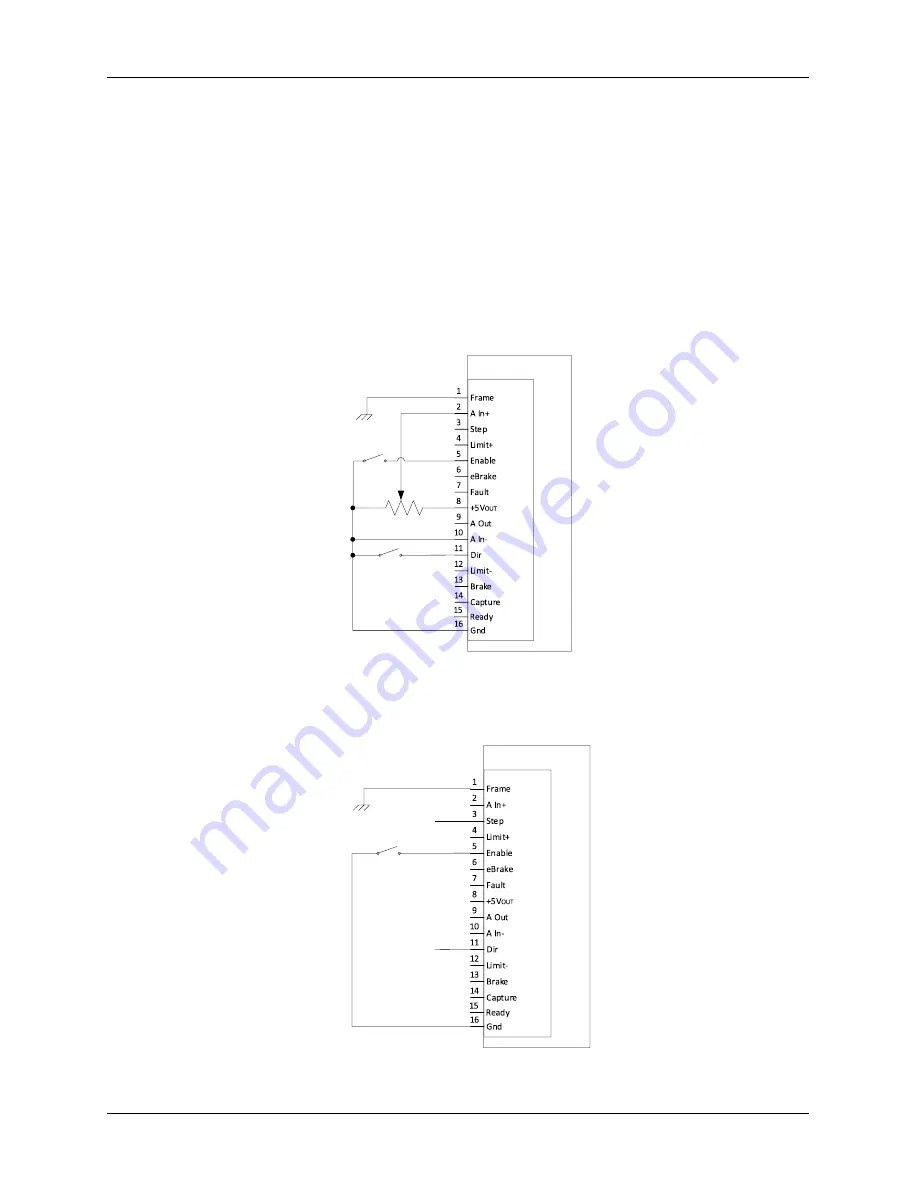
9.2.1
Typical I/O Connections for BLDC and PMDC motors
A basic example using a switch for the Enable signal, a potentiometer for analog speed/torque command
and a switch to change motor direction is shown in Figure 21.
Drive
J5
Drive
Enable
Command
(Speed or Torque)
10K
Command
Direction
Figure 21: Typical drive I/O connections needed to operate BLDC and PMDC motors
9.2.2
Typical I/O Connections for Stepper motor
A basic example using a switch for the Enable signal and digital pulse input for Step and Direction from a
controller is shown in Figure 22.
Drive
J5
Drive
Enable
Direction
(From Controller)
Step
(From Controller)
Figure 22: Typical drive I/O connection needed to operate stepper motor


