VARIPLEX
TM
-B
VARIPLEX
TM
-B
2
back slot under the adjustment bracket.
3. Adjust the horizontal position and se-
curely tighten all the bolts so that the mid/
high subassembly can not inadvertently
rotate.
4. Now loosen the two vertical adjustment
bolts just enough so the adjustment
guides will slide within the adjustment
slot. Adjust the vertical angle, by tilting
the mid/high subassembly,
which will
slide the adjustment bolts along the slot
as shown in figure 1.
Figure 1— Mounting the
HPK-Variplex
TM
-B (pre-assembled mid/
high unit)
5. The aiming point of the mid/high subas-
sembly horn separates the mid-frequency
section from the high-frequency section,
(see figure 1). For proper imaging, this
point should be positioned just above the
vertical center line of the screen (typi-
cally 0.6 of the overall screen height),
(see figure 2). Then tilt vertically to align
with the head of the person in the last
seat of the theater, (See figure 2), and
tighten the vertical adjustment bolts, so
the mid/high subassembly can not inad-
vertently tilt backwards.
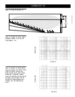
Frequency Response
Figure 4 shows the Variplex
TM
-B frequency
response with a swept sine-wave signal,
4 volts at 500 Hz, in an anechoic (echo free)
environment. The microphone was at a dis-
tance of 3.0 m (10 ft), on an axis with the aim-
ing point of the mid/high-frequency unit.
Aiming
Point
Use longer bolts
in back slot when
mounting the
HPK-Variplex-B
Front of TL606DMT
Bolt Layout for the TL606DMT
Remove Only These Bolts
Back Edge of the Mid/High
sub-assembly Baseboard
(HPK-Variplex-B)
Pivot Point
Loosen for
vertical
adjustment
Loosen for horizontal
adjustment


