14
en | Input panel and DSP
PXM-12MP Powered Monitor
2019-10 | v01 | F.01U.363.983
Installation manual
Electro-Voice
4
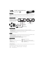
Input panel and DSP
4.1
Input panel controls
The input panel has a combination of controls and connectors for a wide variety of control and
configuration.
PUSH FOR DSP
MAINS IN
OFF
ON
INPUT 1
INPUT 2
INPUT 3
LINE MIC
LINE MIC
AUX IN
MASTER VOLUME
MIX OUT
THRU
2
1
3
6
7
8
5
4
9
PXM-12MP
12” COAXIAL MONITOR
1.
LCD
– DSP control and monitoring interface.
2.
MASTER VOLUME
- Contextual rotary and push knob that is used to adjust and navigate
the DSP menu and to adjust parameters (for example Master Gain).
3.
INPUT LEVEL
- Rotary knob used to adjust the level of the corresponding input. The
detent 12 o’clock position represents unity level (no gain or attenuation). Rotate the knob
to the left to attenuate LINE level sources, or rotate to the right to add gain to MIC level
sources. There is an input level control for INPUT 1, INPUT 2, and INPUT 3.
4.
POWER
– AC switch for switching the power ON or OFF. The LCD screen lights up when
the power is turned ON, after approximately 3 seconds.
5.
MIX OUT
- A post-input level sum of all three input channels. This allows for the ‘mix’ to
be sent to a secondary device, such as a PA or recording device. It can be adjusted in
DSP to output a stereo signal (L+R) or an isolated RIGHT channel. This is ideal for
connecting LEFT mains to RIGHT mains in a PA configuration.
6.
THRU
- An output that is parallel to INPUT 1. This is not affected by the DSP of the
system. It is used to daisy-chain the signal of INPUT 1 to an external device.
7.
INPUT 1, 2
- Balanced MIC/LINE XLR/TRS inputs to connect a line level signal source
(such as mixer, etc.) or a microphone. Whenever possible, balanced signal feed is always
preferable to guard against potential noise.
8.
INPUT 3
- Unbalanced stereo RCA input to connect LINE-level signal sources, such as
mobile devices or media players.
9.
MAINS IN
- The device receives its power supply via the MAINS IN socket. Use the
included IEC power cord to connect the system to a stable, grounded power source.
Connect the device only to an electrical outlet that is capable of providing the voltage and
current outlined on the product label and system specifications.
Содержание PXM-12MP Series
Страница 1: ...PXM 12MP Powered Monitor PXM 12MP EU PXM 12MP US en Installation manual...
Страница 2: ......
Страница 30: ...30 Technical data PXM 12MP Powered Monitor 2019 10 v01 F 01U 363 983 Installation manual Electro Voice...
Страница 31: ......