10
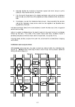
6. Carefully identify the locations of maximum signal, and mark and join up the
positions of the transverse bars as before.
7. Turn the search head back to its original orientation and re-scan the lengthwise
bars to make sure that none of the signals were false indications from transverse
bars.
8. If necessary, re-scan the transverse bars as well. Keep repeating the process
until all the indications make sense, either as real signals or as probable false
signals from other bars.
This basic technique will work for most situations in which the bars are not too congested
and are not touching.
Little or no signal is obtained when the search head is in the exact centre of a rectangle
formed by four bars. The centre of the search head under these conditions marks a
probable safe place to drill (but check also for buried bolts - see section 5.10).
Crossing-points produce a signal from each bar, and should be avoided when mapping
out the bars.
3.4 Welded mesh and joined bars
With
isolated
reinforcing bars, the eddy currents are induced within the individual bars
(Figure 3).
Welded
mesh reinforcing creates current loops which produce additional
strong indications (Figure 7).
Figure 7 Welded mesh fabric
Содержание Protovale CoverMaster CM52
Страница 1: ...Elcometer P350 Protovale CM52 Covermeter Operating Instructions...
Страница 4: ......
Страница 25: ...22 Figure 12 Reference graph for recommended method of estimating bar size...
Страница 27: ...24 Figure 13 Example worksheet...


