I02-243 User & maintenance manual
Version 03
(translation of the original manual)
of
TLM1500 ITS 24 V
Page
29
37
10.2
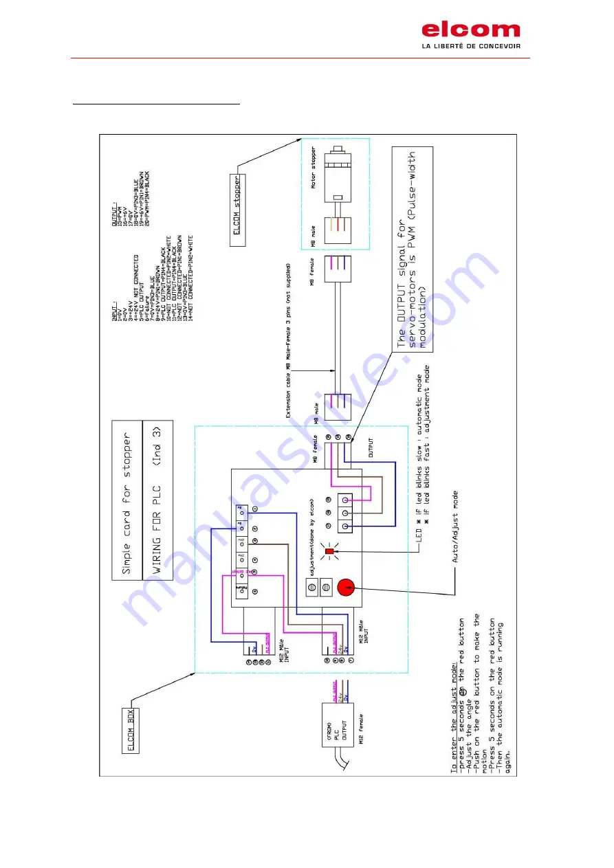
Wiring of the control box of the stoppers
Wiring schematic PLC for a stopper :
Страница 1: ...Modular transfer system 24 Volts ITS TLM 1500 User maintenance manual I02 243 Translation of the original manual version 03...
Страница 2: ...red by Approved by 00 07 08 17 Initial O CELARD M MALEO 01 14 09 17 Modification of security instructions O CELARD M MALEO 02 23 01 18 Precision on motor wiring O CELARD M MALEO 03 18 09 18 Added info...
Страница 3: ...ositioning unit 5 3 4 Double cam 6 3 5 Derivation 7 3 6 Carrier 8 4 Maintenance 9 4 1 Belts wear 9 4 2 Passageways of workpiece carriers 9 4 3 Pins 9 4 4 Wear of the belt guide 9 4 5 Transfert parts 1...
Страница 4: ...e the electrical stoppers see schematic simple card for stopper 27 10 2 Wiring of the control box of the stoppers 29 10 3 Connectic required to wire the doubles cams and derivations 31 10 4 Wiring of...
Страница 5: ...xploded view of the motorized equipment However the following standards are considered for the design of elcom transfers 2006 42 CE directive related to machine systems 73 23 CE directive related to e...
Страница 6: ...between the belt is the support to prevent from any accident During the manipulation or using of the working transfer line be careful of pinching areas indicated by this pictogram 1 6 Motor s safety...
Страница 7: ...ers documentation 2 TECHNICAL CARACTERISTICS Maximum weight on workpiece carrier 4 kg except workpiece carrier Maximum weight accumulation on stopper 35 kg for a maximum stretch of 3 meters Electric t...
Страница 8: ...in perfect condition 3 2 Stopper 1 Place the stopper right in the middle of the two profiles of the system 2 Put the workpiece carrier in contact of the stopper 3 Adjust the presence detection range...
Страница 9: ...the stopper right in the middle of the two profiles of the system 2 The presence detection range is preset 3 The positioning unit has to be fixed on a frame and not under the transfer 4 Fix the trans...
Страница 10: ...I02 243 User maintenance manual Version 03 translation of the original manual of TLM1500 ITS 24 V Page 6 of 37 3 4 Double cam See overall drawing and assembly N 150 21 000 E...
Страница 11: ...User maintenance manual Version 03 translation of the original manual of TLM1500 ITS 24 V Page 7 of 37 3 5 Derivation See overall drawing and assembly N 150 07 000 E Right version et 150 13 000 E Left...
Страница 12: ...lation of the original manual of TLM1500 ITS 24 V Page 8 of 37 3 6 Carrier 1 Check the function of the springs and the pins under the workpiece carrier 2 Check that no part goes over the lower surface...
Страница 13: ...lt and especially the welding area 4 2 Passageways of workpiece carriers The friction of the pins while operating can make some marks appear Those marks may over the long term require the part replace...
Страница 14: ...ation of the original manual of TLM1500 ITS 24 V Page 10 of 37 4 5 Transfert parts Every 200 hours Remove dust from the whole system Use the product r f 800 00 003 polish plastique Air Industry 2101 4...
Страница 15: ...ery 1 000 hours Clean and lubricate guiding shafts Take off the stopper Rep 3 by unscrewing 2 CHC M4 Rep 4 Take off the index plate Rep 1 by unscrewing the CHC M4 Rep 2 Clean and lubricate the guiding...
Страница 16: ...37 4 8 Double cam Every 5 000 hours Clean all double cams 4 9 Derivation Every 5 000 hours Clean all derivations 4 10 Other elements of the transfert Other elements do not require a specific maintena...
Страница 17: ...5 CHANGEOUT OF THE 24V DRIVE MOTOR Shut down the machine that integrate the transfer system Disconnect the wires of the drive to replace 5 1 Unit with PAPST drive motor Take off the drive motor suppo...
Страница 18: ...age 14 of 37 Take of the part Rep 8 fixed by 4 screws CHC M5 Rep 10 Note Please be sure to note the orientation of this part on the drive in order to put the new drive in the correct position Take off...
Страница 19: ...on in the other way in order to mount the new drive motor Note in order to ease the positonning of the new drive motor loosen the belt Rep 7 at the maximum and present the drive motor with an angle wi...
Страница 20: ...l manual of TLM1500 ITS 24 V Page 16 of 37 5 2 Unit with CROUZET motor drive Take off the drive motor support Rep 8 fixed by 4 screws CHC M5 Rep 9 see picture below and the hood Rep 13 fixed by 4 scre...
Страница 21: ...TS 24 V Page 17 of 37 Take of the pinion Rep 5 fixed by a screws CHC M4 Rep 6 and the washer Rep 11 Take of the part Rep 8 fixed by 4 screws CHC M5 Rep 10 Note Please be sure to note the orientation o...
Страница 22: ...way in order to mount the new drive motor Note in order to ease the positoning of the new drive motor loosen the belt Rep 7 at the maximum and present the drive motor with an angle with regard to the...
Страница 23: ...OF THE DRIVE MOTOR OF INDEX UNIT 24V Shut down the machine that integrate the transfer system Disconnect the wires of the drive to replace Take off the chasing Rep 21 fixed by 4 screws CHC M4 Rep 22...
Страница 24: ...03 translation of the original manual of TLM1500 ITS 24 V Page 20 of 37 Take off the support motor Rep 8 fixed by 4 srews CHC M5 Rep 7 Mounting of the drive motor Do all operation in the other way in...
Страница 25: ...7 7 CHANGEOUT THE TOOTHED BELT The new toothed belt is already mounted welded Take off the worn belt and put the new one respecting the flexion on the sprocket and under the guide belt Tense the belt...
Страница 26: ...omposed of the following pins PIN 12 Connected to the 24 V PIN 3 Speed of 9m min IN1 wired on the 24V PIN 4 Speed of 12m min IN2 wired on the 24 V PIN 3 4 Speed of 16 m min Vitesse d avance de 16 m mn...
Страница 27: ...a brown wire for the output pulse a purple wire for the output torque limit reached a red wire for the output direction of movement CAREFUL the brown wire and black wire of the power cable and the gre...
Страница 28: ...a start or in case of emergency stop 6 INPUT IN E6 24V DC for power supply and ok for control Permanent 7 GND 8 GND WHITE BLACK 9 OUTPUT OUT S1 Position OK 10 OUTPUT OUT S2 Motor not connected failur...
Страница 29: ...I02 243 User maintenance manual Version 03 translation of the original manual of TLM1500 ITS 24 V Page 25 of 37 Program Install the software with file Setup_DCmind Soft_V_Elcom msi...
Страница 30: ...I02 243 User maintenance manual Version 03 translation of the original manual of TLM1500 ITS 24 V Page 26 of 37...
Страница 31: ...THE 24V STOPPERS 10 1 Connectic required to wire the electrical stoppers see schematic simple card for stopper To wire an electric stopper you ll need An extender M8 3 pins with a connector male and a...
Страница 32: ...he other extremity of this cable might be with a connector M12 or wired directly according to the cabling required on the project Note each small control box is equiped on the left side by two connect...
Страница 33: ...I02 243 User maintenance manual Version 03 translation of the original manual of TLM1500 ITS 24 V Page 29 of 37 10 2 Wiring of the control box of the stoppers Wiring schematic PLC for a stopper...
Страница 34: ...I02 243 User maintenance manual Version 03 translation of the original manual of TLM1500 ITS 24 V Page 30 of 37 Wiring schematic FIELD BUS for a stopper...
Страница 35: ...nectic required to wire the doubles cams and derivations To wire the double cam 24V or a derivation 24V you ll need Two extender M8 pins with a connector male and a connector female straight or elbow...
Страница 36: ...r extremity of this cable might be with a connector M12 or wired directly according to the cabling required on the project Note each small control box is equiped on the left side by two connectors M12...
Страница 37: ...enance manual Version 03 translation of the original manual of TLM1500 ITS 24 V Page 33 of 37 10 4 Wiring of the control box of the double cam 24V or derivation 24V Wiring schematic PLC for a double c...
Страница 38: ...I02 243 User maintenance manual Version 03 translation of the original manual of TLM1500 ITS 24 V Page 34 of 37 Wiring schematic FIELD BUS for a double cam or a derivation...
Страница 39: ...malfunction if some spare parts have been used without the validation of elcom Elcom reserves the right to make improvements and technical modifications without any further notice 12 CUSTOMER SERVICE...
Страница 40: ...Maintenance of the modular transfer system TLM 1500 ITS 24V Fr quency Action Components Chapter 200 hours Dusting Transfer system elements 4 5 500 hours Control Belts Belt guide Workpiece carrier 4 1...
Страница 41: ...ications Our company is recognized according to the following ISO standards and their respective evolutions since our first certification Quality Management through ISO 9001 since 2002 Environmental M...