ELCO S.r.l. - ELK 38 - OPERATING INSTRUCTIONS - Vr. 02 - ISTR 06261 - PAG. 3
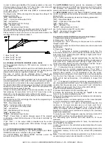
Release the key and by using the “UP” and “DOWN” keys, it will be
possible to select a new group (if present).
To exit the programming mode, no key should be pressed for
approx. 20 seconds, or keep the “UP” or “DOWN” pressed until exit
from the programming mode is obtained.
To enter the menu "ConF" a PASSWORD is required.
At this request, enter, using keys “UP” and “DOWN”, the number
reported on the last page of this manual and push key “P”.
If an incorrect password is entered, the instrument returns to the
previous control state.
If the password is correct, the display will visualise the code
identifying the first group of parameters (“
]
SP “) and with keys “UP”
and “DOWN” it will be possible to select the desired group of
parameters
The programming and exit modes for the “ConF” menu are the
same as those described for menu “OPEr”.
2.3 - PARAMETERS PROGRAMMING LEVELS
The menu “OPEr” normally contains the parameters used to
program the Set Point; however it is possible to make all desired
parameters appear or disappear on this level, by following this
procedure:
Enter the menu “ConF” and select the parameter to be made
programmable or not programmable in the menu “OPEr”.
Once the parameter has been selected, if the LED SET is switched
off, this means that the parameter is programmable only in the
menu “ConF”, if instead the LED is on, this means that the
parameter is also programmable in the menu “OPEr”.
To modify the visibility of the parameter, push key “U” : the LED SET
will change its state indicating the parameter accessibility level (on =
menu ”OPEr” and “ConF”; off = menu “ConF” only).
The active Set Point and the alarm thresholds will only be visible on
the Set Point fast programming level (described in par. 2.1) if the
relative parameters are programmed to be visible (i.e. if they are
present in the menu “OPEr”).
The possible modification of these Sets, with the procedure
described in par. 2.1, is instead subordinate to what is programmed
in par. “Edit” (contained in the group “
]
PAn “).
This parameter can be programmed as :
=SE : The active Set Point can be modified while the alarm
thresholds cannot be modified.
=AE : The active Set Point cannot be modified while the alarm
thresholds can be modified
=SAE : Both the active Set Point and the alarm thresholds can be
modified
=SAnE : Both the active Set Point and the alarm thresholds cannot
be modified
2.4 - CONTROL STATES
The controller can act in 3 different ways : automatic control (rEG),
control off (OFF) and manual control (OPLO).
The instrument is able to pass from one state to the other :
- by selecting the desired state from the main selection menu suing
the keyboard.
- By using the key “U” on the keyboard; suitably programming par.
“USrb” (“USrb” = tunE; “USrb” = OPLO; “USrb” = OFF) it is possible
to pass from “rEG” state to the state programmed on the parameter
and vice versa.
- Automatically (the instrument swaps into "rEG" state at the and of
the auto-tuning execution)
When switched on, the instrument automatically reassumes the
state it was in when it was last switched off.
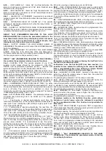
AUTOMATIC CONTROL (rEG) – Automatic control is the normal
functioning state of the controller.
During automatic control it is possible to visualize the control power
on the display by pushing key “UP”.
The range of the power values goes from H100 (100% of the output
power with reverse action) to C100 (100% of the output power with
direct action).
CONTROL OFF (OFF) – The instrument can be swapped into the
“OFF” state, i.e. the control and the relative outputs are deactivated.
The alarm outputs are instead working normally.
BUMPLESS MANUAL CONTROL (OPLO) – By means of this
option it is possible to manually program the power percentage
given as output by the controller by deactivating automatic control.
When the instrument is swapped to manual control, the power
percentage is the same as the last one supplied and can be
modified using the “UP” and “DOWN” keys.
As in the case of automatic control, the programmable values range
from H100 (+100%) to C100 (-100%).
To return to automatic control, select "rEG" in the selection menu.
2.5 - ACTIVE SET POINT SELECTION
This instrument permits pre-programming of up to 4 different Set
points (“SP1”, “SP2”, “SP3”, “SP4”) and then selection of which
one must be active. The maximum number of Set points is
determined by the par. "nSP" located in the group of parameters “
]
SP “.
The active Set point can be selected :
- by parameter "SPAt" in the group of parameters “
]
SP “.
- by key “U” if par. "USrb" = CHSP
- Automatically between SP1 and SP2 if a time “dur.t” (see par. 4.8)
has been programmed.
Set Points “SP1”, “SP2”, “SP3”, “SP4” will be visible depending on
the maximum number of Set Points selected on par. “nSP” and they
can be programmed with a value that is between the value
programmed on par. “SPLL” and the one programmed on par.
“SPHL”.
Note : in all the following examples the Set point is indicated as
"SP", however the instrument will act according to the Set point
selected as active.
3 - INFORMATION ON INSTALLATION AND USE
3.1 - PERMITTED USE
The
instrument
has
been
projected
and
manufactured as a measuring and control device to
be used according to EN61010-1 for the altitudes
operation until 2000 ms.
The use of the instrument for applications not
expressly permitted by the above mentioned rule must adopt all the
necessary protective measures.
The instrument CANNOT be used in dangerous environments
(flammable or explosive) without adequate protection.
The installer must ensure that EMC rules are respected, also after
the instrument installation, if necessary using proper filters.
Whenever a failure or a malfunction of the device may cause
dangerous situations for persons, thing or animals, please
remember that the plant has to be equipped with additional devices
which will guarantee safety.
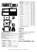
3.2 – MECHANICAL MOUNTING
The instrument, in case 33 x 75 mm, is designed for flush-in panel
mounting.
Make a hole 29 x 71 mm and insert the instrument, fixing it with the
provided special bracket.
We recommend that the gasket is mounted in order to obtain the
front protection degree as declared. Avoid placing the instrument in
environments with very high humidity levels or dirt that may create
condensation or introduction of conductive substances into the
instrument.
Ensure adequate ventilation to the instrument and avoid installation
in containers that house devices which may overheat or which may
cause the instrument to function at a higher temperature than the
one permitted and declared.


