background image

ELCO S.r.l. - ELK 38 - OPERATING INSTRUCTIONS - Vr. 02 - ISTR 06261 - PAG. 1


MICROPROCESSOR-BASED 

DIGITAL  

ELECTRONIC CONTROLLER


OPERATING INSTRUCTIONS 

Vr. 02 (ENG) - cod.: ISTR 06261


EL.CO. S.r.l.


VIA MARCONI, 49 

36030 PIEVEBELVICINO (VI) ITALY 

TEL.:  +39 0445 661722 

FAX: +39 0445 661792 

internet : http:\\www.elco-italy.com 

e-mail: [email protected] 


FOREWORD
This  manual  contains  the  information  necessary  for  the  product  to 
be  installed  correctly  and  also  instructions  for  its  maintenance  and 
use; we therefore recommend that the utmost attention is paid to the 
following instructions.  
Though  this  manual has been issued with the greatest care, ELCO 
S.r.l.  will not take any responsibility deriving from its use.  
The  same  applies  to  each  person  or  Company  involved  in  the 
issuing of this manual.  
This  document  is  the  exclusive  property  of  ELCO  S.r.l.    which 
forbids  any  reproduction  and  divulgation  ,  even  in  part,  of  the 
document, unless expressly authorized.  
ELCO  S.r.l.    reserves  the  right  to  make  any  formal  or  functional 
changes at any moment and without  any notice. 


INDEX 

1 

INSTRUMENT DESCRIPTION 

1.1 

GENERAL DESCRIPTION 

1.2 

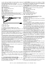
FRONT PANEL DESCRIPTION 

2 

PROGRAMMING 

2.1 

FAST PROGRAMMING OF SET POINT  

2.2 

SELECTION  OF  CONTROL  STATE  AND  PARAMETER 
PROGRAMMING  

2.3 

PARAMETER PROGRAMMING LEVELS 

2.4 

CONTROL STATES 

2.5 

ACTIVE SET POINT SELECTION 

3 

INFORMATION ON INSTALLATION AND USE  

3.1 

PERMITTED USE 

3.2 

MECHANICAL MOUNTING 

3.3 

ELECTRICAL CONNECTIONS 

3.4 

ELECTRICAL WIRING DIAGRAM 

4 

FUNCTIONS 

4.1 

MEASURING AND VISUALIZATION 

4.2 

OUTPUTS CONFIGURATION 

4.3 

ON/OFF CONTROL 

4.4 

NEUTRAL ZONE ON/OFF CONTROL 

4.5 

SINGLE ACTION PID CONTROL 

4.6 

DOUBLE ACTION PID CONTROL 

4.7 

AUTO-TUNING AND SELF-TUNING FUNCTIONS 

4.8 

REACHING  OF  SET  POINT  AT  CONTROLLED  SPEED 
AND  AUTOMATIC  COMMUTATION  BETWEEN  TWO 
SET POINTS 

4.9 

SOFT-START FUNCTION 

4.10  ALARM FUNCTIONS 

4.10.1  ALARM OUTPUT CONFIGURATION 
4.10.2  ALARM HYSTERESIS 

4.11  LOOP BREAK ALARM FUNCTION 
4.12  FUNCTION OF KEY “U” 
4.13  PARAMETERS CONFIGURATION BY KEY01 

5 

PROGRAMMABLE PARAMETERS 

5.1 

PARAMETERS TABLE 

5.2 

PARAMETERS DESCRIPTION 

6 

PROBLEMS , MAINTENANCE AND GUARANTEE 

6.1 

ERROR SIGNALLING 

6.2 

CLEANING 

6.3 

GUARANTEE AND REPAIRS 

7 

TECHNICAL DATA 

7.1 

ELECTRICAL DATA 

7.2 

MECHANICAL DATA 

7.3 

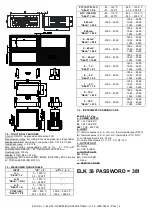
MECHANICAL  DIMENSIONS,  PANEL  CUT-OUT  AND 
MOUNTING 

7.4 

FUNCTIONAL DATA 

7.5 

MEASUREMENT RANGE TABLE 

7.6 

INSTRUMENT ORDERING CODE 


1 - INSTRUMENT DESCRIPTION 

 
1.1 - GENERAL DESCRIPTION
 
ELK  38  is  a  “single  loop”  digital  microprocessor-based  controller, 
with  ON/OFF,  Neutral  Zone  ON/OFF,  PID  single  action,  PID  dual 
action  (direct  and  reverse)  control  and  with  AUTO-TUNING  FAST 
function,  SELF-TUNING  function  and  automatic  calculation  of  the 
FUZZY OVERSHOOT CONTROL parameter for PID control. 
The PID control has a particular algorithm with TWO DEGREES OF 
FREEDOM 
that optimises the instrument’s features independently in 
the event of process disturbance and Set Point variations. 
The  process  value  is  visualized  on  4  red  displays,  while  the  output 
status is indicated by 2 LED displays. 
The  instrument  is  equipped  with  a  3  LED  programmable  shift 
indexes . 
The  instrument  provides  for  the  storage  of  4  Set  Points  and  can 
have up to 2 outputs: relay type or can drive solid state relays type 
(SSR). 
Depending on the model required the input accept: 
C:  Thermocouples  temperature  probes  (J,K,S  and  ELCO  IRS 
Infrared  sensors),  mV  signals  (0..50/60  mV,  12..60  mV), 
Thermoresistances PT100. 

ELK 38


Содержание ELK 38

Страница 1: ...ACTION PID CONTROL 4 6 DOUBLE ACTION PID CONTROL 4 7 AUTO TUNING AND SELF TUNING FUNCTIONS 4 8 REACHING OF SET POINT AT CONTROLLED SPEED AND AUTOMATIC COMMUTATION BETWEEN TWO SET POINTS 4 9 SOFT STAR...

Страница 2: ...er two seconds in the same condition the changing speed increases in order to allow the desired value to be reached rapidly Once the desired value has been reached by pushing key P it is possible to e...

Страница 3: ...of the controller During automatic control it is possible to visualize the control power on the display by pushing key UP The range of the power values goes from H100 100 of the output power with rev...

Страница 4: ...nearization J Ir J or K Ir CA for thermoresistances Pt100 IEC Pt1 or thermistors PTC KTY81 121 Ptc or NTC 103AT 2 ntc for normalised signals in current 0 20 mA 0 20 or 4 20 mA 4 20 for normalised sign...

Страница 5: ...value SP HSEt Vice versa in case of direct action or cooling Func CooL it deactivates the output when the process value reaches SP HSEt in case of symmetrical hysteresis or SP in case of asymmetrical...

Страница 6: ...control monitoring and the continuous calculation of the parameters during control Both functions automatically calculate the following parameters Pb Proportional Band tcr1 Cycle time of the output 1r...

Страница 7: ...on only works through PID control and allows the limitation of control power when the instrument is switched on for a programmable period of time This is useful when the actuator driven by the instrum...

Страница 8: ...ument is in alarm condition the alarm is not activated It will be activated only when the process value is in non alarm conditions and then back in alarm conditions ALARM DELAY the alarm output may be...

Страница 9: ...CONFIGURATION BY KEY01 The instrument is equipped with a connector that allows the transfer from and toward the instrument of the functioning parameters through the device ELCO KEY01 with 5 poles conn...

Страница 10: ...arm AL1L 9999 9999 27 HAL1 Alarm AL1 hysteresis OFF 9999 1 28 AL1d Activation delay of alarm AL1 OFF 9999 sec OFF 29 AL1i Alarm AL1 activation in case of measuring error no yES no Group LbA parameters...

Страница 11: ...defines the error conditions of the input allowing the instrument to give the power programmed on par OPE as output The possibilities are Or the condition occurs in case of over range or probe breakag...

Страница 12: ...with Func HEAt than SP SP 2 or higher with Func CooL than SP SP 2 OFF Autotuning disabled When it s occurring an Autotuning cycle led AT blinks SELF SELF TUNING ENABLE Parameter used to enable yES or...

Страница 13: ...y to repeat the auto tuning LbA Loop control interrupted Loop break alarm Check the working of probe and actuator and swap the instrument to rEG control ErEP Possible anomaly of the EEPROM memory Push...

Страница 14: ...C 58 0 230 0 F 0 20 mA SEnS 0 20 1999 9999 199 9 999 9 19 99 99 99 1 999 9 999 4 20 mA SEnS 4 20 1999 9999 199 9 999 9 19 99 99 99 1 999 9 999 0 50 mV SEnS 0 50 1999 9999 199 9 999 9 19 99 99 99 1 99...

Отзывы: