4. ADJUSTMENT
23
4. ADJUSTMENT
4-1. Screen Adjustment
NOTE
•
Allow the LCD monitor to stabilize for at least 30 minutes before making image adjustments.
The monitor displays the digital input image correctly based on its pre-setting data.
Analog Input
Screen adjustments for the LCD monitor should be used in suppressing screen flickering and also
for adjusting the screen to its proper position. There is only one correct position for each display mode.
It is also recommended to use the ScreenManager function when first installing the display or
whenever changing the system. For convenience, an easy set-up Program installed on the utility disk to
assist in the set-up procedure is provided.
Adjustment Procedure
1
Touch the Auto Adjustment Switch on the control panel.
The message appears and remains on the screen for 5 seconds. While the message is on the screen,
touch the Auto Adjustment switch again to automatically adjust the clock, phase, screen position
and resolution. If you do not wish to do adjust the screen, do not touch the Auto Adjustment
switch again.
NOTE
•
The Auto adjustment function is intended for use on the Macintosh and on AT-compatible PC
running Windows. It may not work properly in either of the following cases. When running an
AT-compatible PC on MS-DOS (Not windows). The background color for the "wall paper" or
"desktop" pattern is set to black.
•
It cannot work correctly using with some graphics cards.
If the appropriate screen cannot be made by using the Auto Adjustment switch, adjust the screen through
the following procedures. If the appropriate screen can be made, proceed to 4. Range Adjustment .
2
Run the "Screen Adjustment Program".
Having read the "Readme.txt" file, run the "Screen Adjustment Program" in the enclosed EIZO
LCD Utility Disk. Step by step, adjustment is provided by the wizard guide. (If using the Windows,
the program can be directly run from the menu screen of the CD-ROM.)
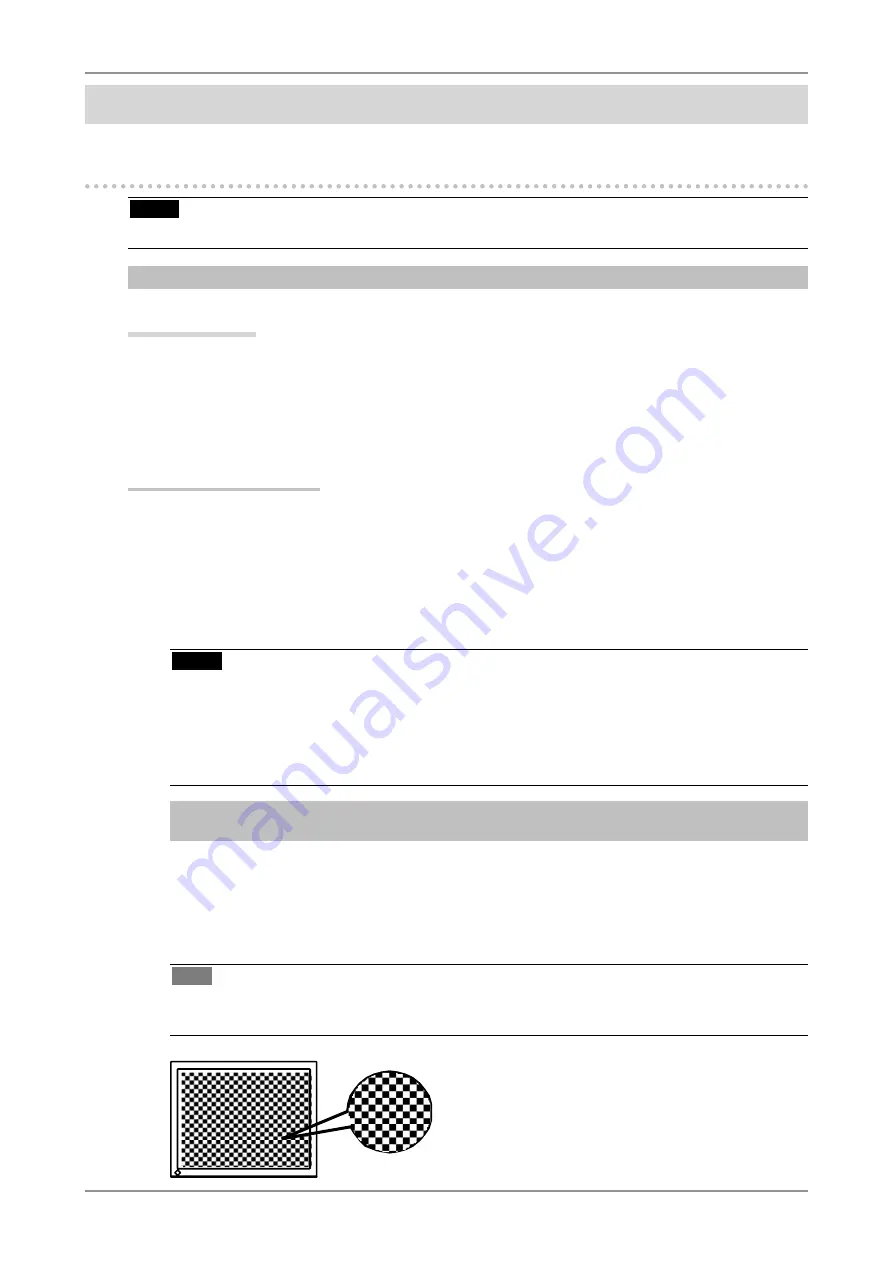
Tips
•
If the user's operating system has no utility disk (e.g. OS/2), we recommend setting the desktop
pattern to that as shown in the diagram on the following.
Содержание ColorEdge CE210W
Страница 41: ...9 SPECIFICATIONS 41 Dimensions CE210W mm inch...
Страница 52: ......


