EINHELL Expert 11013 Скачать руководство пользователя страница 10

GB

- 10 -

Please note that our equipment has not been de-

signed for use in commercial, trade or industrial 

applications. Our warranty will be voided if the 

equipment is used in commercial, trade or indust-

rial businesses or for equivalent purposes.

4. Technical data

Speed n

0

 .............................................8,500 min

-1

Cutting circle  ..........................................Ø 24 cm

Max. operating time  .....................  approx. 40 min

Protection class  ................................................III

L

WA

 sound power level  ...............................  88 dB

L

pA

 sound pressure level  ............................  68 dB

B

d


6

..

..

..

..

..

..

..

..

..

..

..

..

..

..

..

..

..

..

..

..

..

..

..

..

y

t

n

i

a

tr

e

c

n

u


Interchangeable battery  .....18 V d. c. / 3000 mAh

........................... (optional: 18 V d. c. / 1500 mAh)

Vibration ..................................................5.8 m/s

2

K uncertainty  .......................................... 2.3 m/s²

Weight  ....................................................... 2.2 kg

Sound pressure level

at the operator‘s ear ............................... 78 dB(A)

B

d


3

..

..

..

..

..

..

..

..

..

..

..

..

..

..

..

..

..

..

..

..

..

..

..

..

y

t

n

i

a

tr

e

c

n

u


Charging unit

Mains voltage  ...............................  230 V ~ 50 Hz

Output

Rated voltage ........................................  21 V d. c.

Rated current  .......................................  3000 mA

The machine may exceed 85 dB (A). The operator 

will require noise protection measures if this is 

the case. The noise was measured in accordance 

with prEN ISO 10518. The value of the vibrations 

emitted by the handle was determined in ac-

cordance with prEN ISO 10518.

Important.

The vibration value changes according to the 

area of application of the electric equipment and 

may exceed the specifi ed value in exceptional 

circumstances.

Reduce noise generation and vibration to a 

minimum!

• 

Use only equipment that is in perfect condi-

tion.

• 

Maintain and clean the equipment regularly.

• 

Adapt your way of working to the equipment.

• 

Do not overload the equipment.

• 

Have the equipment checked if necessary.

• 

Switch off the equipment when not in use.

• 

Wear gloves.

5. Before putting into operation

5.1 Fitting the safety hood (Fig. 3-4)

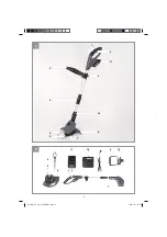
When  fitting the safety hood (Fig. 1/Item 8) make 

sure that the edge guide (Fig. 1/Item 6) is in a po-

sition in which the blade head (Fig. 1/Item 7) does 

not obstruct the fi  tting. Push the guard hood (Fig. 

1/Item 8) in the direction of the arrow onto the 

motor housing as shown in Fig. 3. Make sure that 

it latches in place correctly! Make sure that the 

guard hood is fi  tted as in Fig. 4.

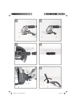
5.2 Height adjustment (Fig. 5)

Undo the union nut (Fig. 5/Item 5) until the grass 

trimmer handle can be moved in and out freely. 

Now set the required working height (Fig. 6) and 

secure the handle in this position by tightening 

the union nut again.

5.3. Fitting the additional handle (Fig. 7)

Fit the additional handle to the mount provided, 

paying attention to the teeth (Fig. 7/Item I & II). 

Then secure the additional handle with the help 

of the screw and the adjustment lock provided. 

Make sure that the compartment for the spare 

blades faces the top of the equipment.

5.4 Adjusting the additional handle (Fig. 8)

Undo the adjustment lock (Fig. 8/Item 3) for the 

additional handle until it can be moved forwards 

and backwards without any great resistance. Set 

the required position and tighten the securing 

screw again.

5.5 Adjusting the angle of tilt of the guide 

handle (Fig. 9)

Press the button for the angle of tilt adjustment 

(Fig. 9/Item K). Now you can set the long handle 

to the required tilt. Release the button and allow 

the handle to lock into position to fi  x the angle of 

tilt. Three di

 erent locking angles are possible.

5.6. Installing the battery (Fig. 10/11)

Press the side pushlock buttons of the battery 

pack as shown in Fig. 10 and push the battery 

pack into the mount provided. When the battery 

pack is positioned as in Fig. 11, make sure that 

the pushlock buttons latch in place! To remove the 

battery pack, proceed in reverse order.

Anl_GE_CT_18_Li_Kit_SPK7.indb   20

14.01.13   13:46

Содержание 11013

Страница 1: ... Li Kit GE CT 18 Li Kit 3 1 0 1 1 r N I 4 7 1 1 1 4 3 r N t r A 3 1 0 1 1 r N I 3 7 1 1 1 4 3 r N t r A 7 GB Original operating instructions Cordless Lawn Trimmer Anl_GE_CT_18_Li_Kit_SPK7 indb 1 14 01 13 13 45 ...

Страница 2: ... 2 1 2 4 6 9 2 1 7 11 10 11 3 13 8 5 1 2 9 6 8 7 4 12 Anl_GE_CT_18_Li_Kit_SPK7 indb 2 Anl_GE_CT_18_Li_Kit_SPK7 indb 2 14 01 13 13 45 14 01 13 13 45 ...

Страница 3: ... 3 3 4 5 6 7 8 6 8 4 I 6 5 II 12 3 Anl_GE_CT_18_Li_Kit_SPK7 indb 3 Anl_GE_CT_18_Li_Kit_SPK7 indb 3 14 01 13 13 45 14 01 13 13 45 ...

Страница 4: ... 4 9 10 K 11 12a 12b 13 13 Anl_GE_CT_18_Li_Kit_SPK7 indb 4 Anl_GE_CT_18_Li_Kit_SPK7 indb 4 14 01 13 13 45 14 01 13 13 45 ...

Страница 5: ... 5 14 15 16 17 18 19 9 9 Anl_GE_CT_18_Li_Kit_SPK7 indb 5 Anl_GE_CT_18_Li_Kit_SPK7 indb 5 14 01 13 13 46 14 01 13 13 46 ...

Страница 6: ... 6 20 1 2 3 4 5 6 Anl_GE_CT_18_Li_Kit_SPK7 indb 6 Anl_GE_CT_18_Li_Kit_SPK7 indb 6 14 01 13 13 46 14 01 13 13 46 ...

Страница 7: ...ut and items supplied 3 Intended use 4 Technical data 5 Before putting into operation 6 Operation 7 Cleaning maintenance and ordering of spare parts 8 Disposal and recycling 9 Faults 10 Charger indicator Anl_GE_CT_18_Li_Kit_SPK7 indb 17 14 01 13 13 46 ...

Страница 8: ...GB 8 Caution Read the operating instructions to reduce the risk of injury Anl_GE_CT_18_Li_Kit_SPK7 indb 18 14 01 13 13 46 ...

Страница 9: ...ompartment for spare blades 13 Lock for rotatable motor head 2 2 Items supplied Open the packaging and take out the equip ment with care Remove the packaging material and any packaging and or transportation braces if available Check to see if all items are supplied Inspect the equipment and accessories for transport damage If possible please keep the packaging until the end of the guarantee period...

Страница 10: ... 8 make sure that the edge guide Fig 1 Item 6 is in a po sition in which the blade head Fig 1 Item 7 does not obstruct the fitting Push the guard hood Fig 1 Item 8 in the direction of the arrow onto the motor housing as shown in Fig 3 Make sure that it latches in place correctly Make sure that the guard hood is fitted as in Fig 4 5 2 Height adjustment Fig 5 Undo the union nut Fig 5 Item 5 until th...

Страница 11: ... 2 Do not allow the grass trimmer near the grass until the switch is pressed i e the grass trim mer is in operation To cut properly swing the machine sideways while moving forwards Keep the grass trim mer inclined at an angle of approx 30 while you do so see Figs 17 and 18 If the grass is long the grass must be cut shorter in stages starting from the tip see Fig 19 Use the guard hood to prevent un...

Страница 12: ...he equipment Spare part number of the required spare part For our latest prices and information please go to www einhell com au 8 Disposal and recycling The equipment is supplied in packaging to pre vent it from being damaged in transit The raw materials in this packaging can be reused or recycled The equipment and its accessories are made of various types of material such as metal and plastic Def...

Страница 13: ...rger from the mains supply Flashing Off Adapted charging The charger is in gentle charging mode For safety reasons the charging is performed less quickly and takes more than 1 hour The reasons can be The battery pack has not been used for a very long time or an already flat battery was further discharged exhaustive discharge The battery pack temperature is outside the ideal range between 25 C and 4...

Страница 14: ...tructions or damage caused by unprofessional installation failure to comply with the operating instructions e g connection to the wrong mains voltage or current type misuse or inappropriate use such as overloading of the product or use of non approved tools or accessories failure to comply with the maintenance and safety regulations ingress of foreign bodies into the product e g sand stones or dus...

Страница 15: ...Anl_GE_CT_18_Li_Kit_SPK7 indb 25 14 01 13 13 46 ...

Страница 16: ...F EH 05 2013 01 Anl_GE_CT_18_Li_Kit_SPK7 indb 26 14 01 13 13 46 ...

Отзывы: