EGS Sola/Hevi-duty Intellislot Скачать руководство пользователя страница 3


English 


INSTALLATION 


Parts required:


Intellislot™ Interface for Relay Contacts card and required cable 
assembly.  


Tools required:


Either #2 (medium) Phillips or small flat head screw driver. 
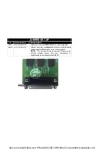
 

1. 

It is suggested, but not necessary, to 
turn the UPS off prior to installation.  
Locate the Intellislot™ Port


on the rear 

panel of your UPS.  (Location and 
orientation can vary according to 
specific UPS model).  


2. 

Remove the two retaining screws of 
the Intellislot™ Port cover plate on the 
UPS back panel

.  Save the screws for 

re-assembly (Step 4).


3. 

The card and slot are keyed to insert in 
one position only.  Initially, the card 
should slide in freely as you carefully 
align screw holes.  As you feel it click 
into place, press firmly to ensure solid 
seating in the slot. 


4. 

Using the screwdriver, secure the card to the UPS chassis with the 
two retaining screws.  Make sure the screws are snug, not tight, to 
avoid damage to the device.


Card and Slot Orientation 


Location of Intellislot


Port 

Buy: www.ValinOnline.com | Phone 844-385-3099 | Email: CustomerService@valin.com

Содержание Sola/Hevi-duty Intellislot

Страница 1: ...USER MANUAL English Communications Card Intellislot Interface for Relay Contacts Buy www ValinOnline com Phone 844 385 3099 Email CustomerService valin com...

Страница 2: ...t and On UPS signals the easy to install card integrates with AS 400 computers additional cable required and other relay contact monitoring systems This advanced power management device is specially d...

Страница 3: ...screws of the Intellislot Port cover plate on the UPS back panel Save the screws for re assembly Step 4 3 The card and slot are keyed to insert in one position only Initially the card should slide in...

Страница 4: ...d if ON UPS inverter power 16 On Battery Closed if ON BATTERY power Utility failure 17 Common UPS Fault Summary Alarm On UPS On Battery On Bypass 18 On Battery Closed if not ON Battery power Utility O...

Страница 5: ...P02 Pin 7 to Pin 17 Allows all relay COMMONS and the ANY MODE SHUTDOWN GROUND to be tied together NOTE This jumper should be removed if there is any external voltage source that may intentionally or i...

Страница 6: ...mber In order to successfully diagnose your individual problem our technicians may require the following installation site and system information Please have it available when you call INSTALLATION SI...

Страница 7: ...repair use beyond rated capacity or improper installation maintenance application or use including without limitation use in a manner contrary to the accompanying instructions or applicable codes WARN...

Отзывы: