Mechanical Operation and Maintenance Manual for ER20-1100 Industrial Robot
20
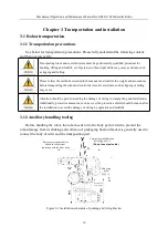
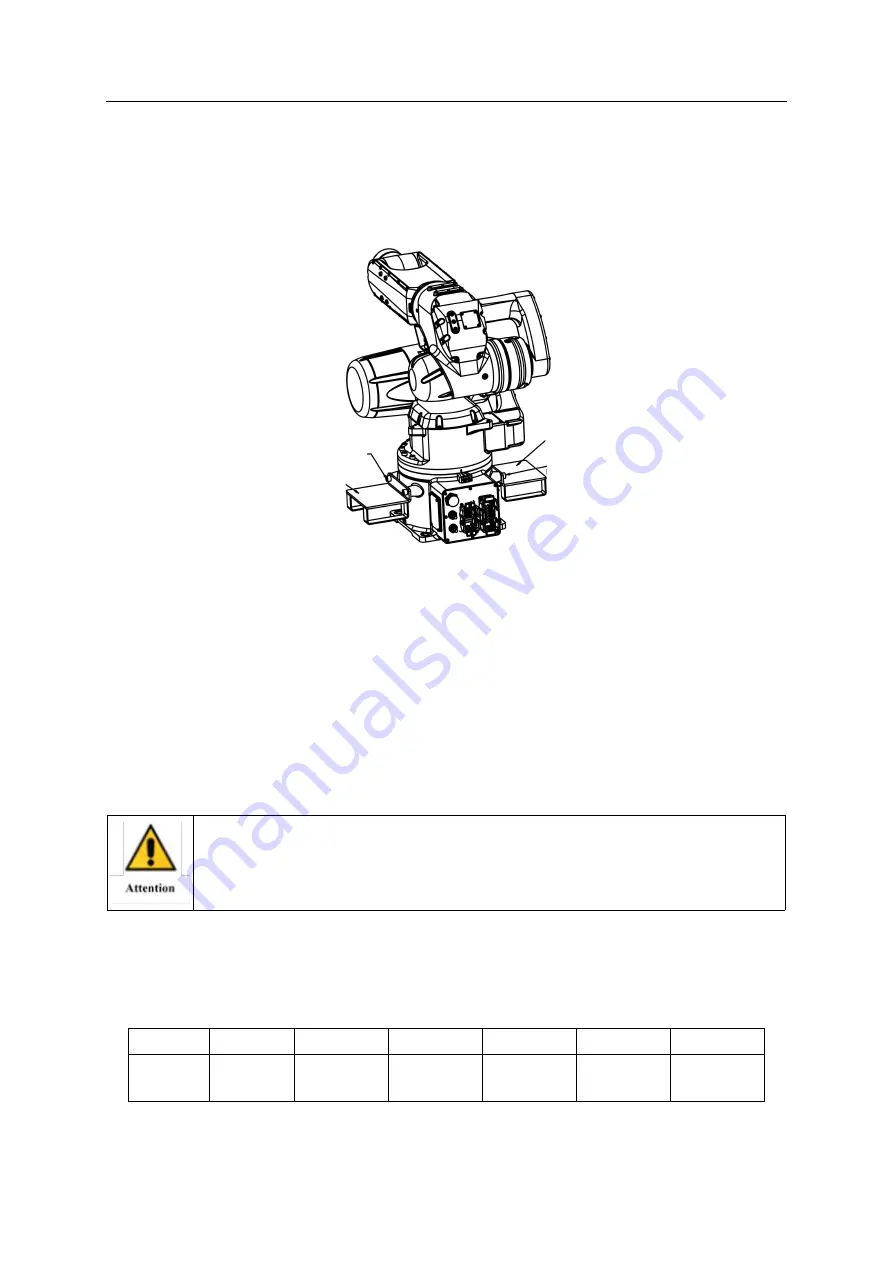
Attention should be paid to observing whether space for fork feet is reserved near the
base of the robot if a forklift is chosen for transporting. Because ER20-1100 does not reserve
space for fork feet, external fork feet should be installed to assist the forklift for transporting.
The fork feet should be removed in time to avoid interference with robot movement.
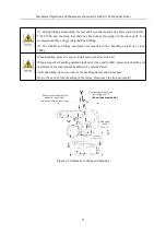
Figure 3-2 Schematic diagram of the fork feet installation
3.1.3 Transporting method
1) Handling method 1
When handling the robot, first set the robot according to the gesture shown in Fig. 2-4,
then install 3 M12 separate ring screws on the main frame and lift it with four flexible lifting
belts. It is suggested that the length of the flexible lifting belts should not be less than 2m, and
rubber hose should be put on the contact part between the lifting belts and the main body of
the robot for protection.
In Figure 3-3 / 3-4, other devices are not installed on the end effector or robot arm. Extra
attention should be paid to once other devices are installed.
2) Handling method 2
Set the robot to the gesture shown in Fig. 3-2 and use the forklift to carry.The angle of
each axis of the handling attitude and gesture is set as follows:
Position
1 axis
2 axis
3 axis
4 axis
5 axis
6 axis
Joint
angle/°
0
70
-70
-180
0
0
Fork feet
(remove
after use)
Fork feet
(remove
after use)
2-M2
×
25
Hexagon socket cap screws
2-M2
×
25
Hexagon socket cap screws


