Mechanical Operation and Maintenance Manual for ER20-1100 Industrial Robot
34
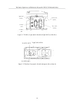
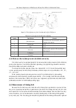
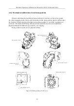
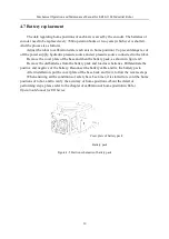
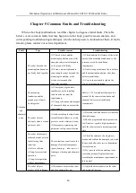
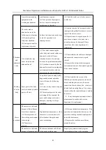
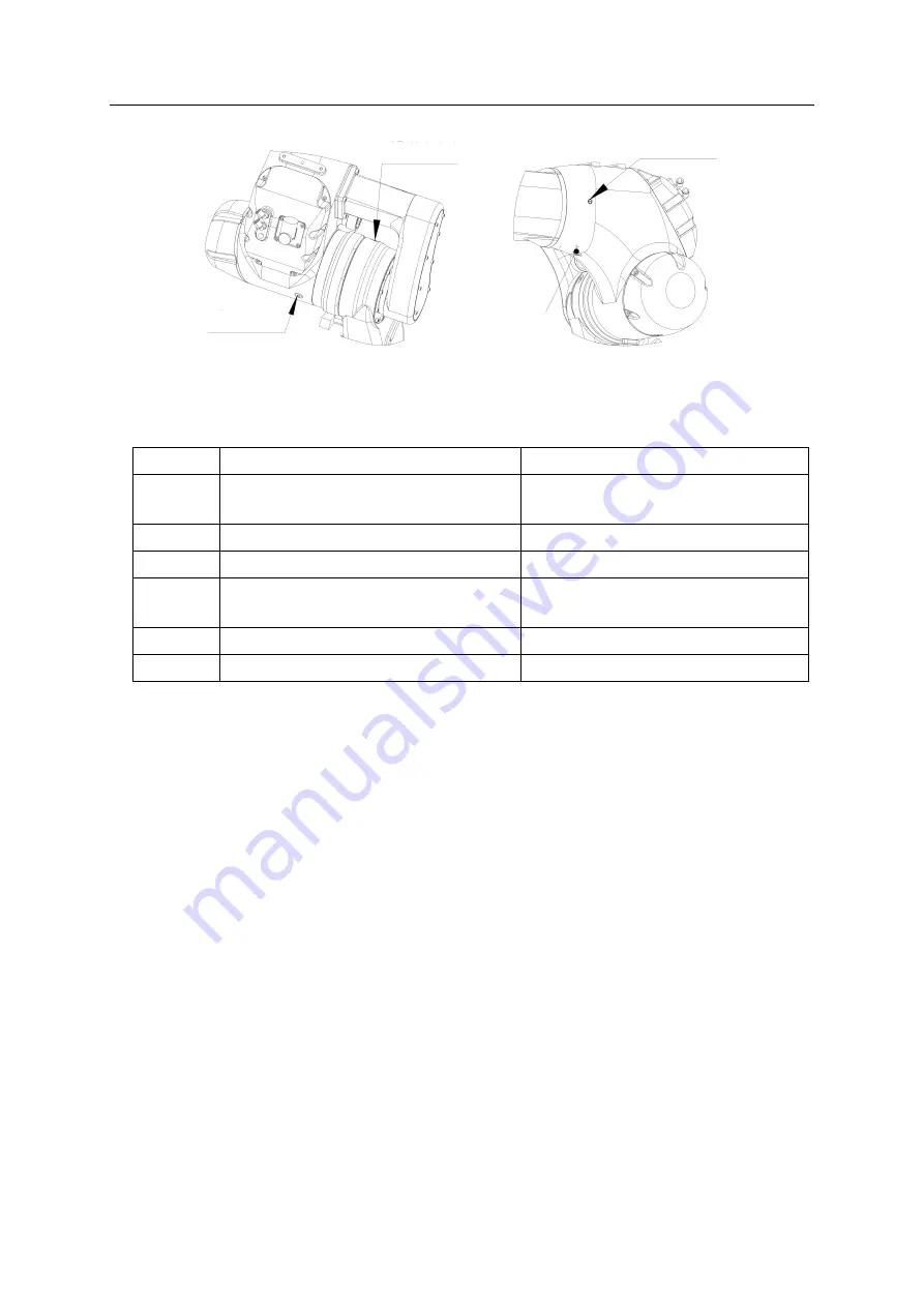
Figure 4-1 Distribution on robot of intake and outlet of lubricant
Table 4-8 Tools required for lubricant replacing
Number
Specification
Remark
1
Lubricant injector
Has the function of measuring the capacity of
lubricant to be injected
2
Injector joint
1 PC
3
Hose
1 PC
4
Poid meter
Measuring the capacity of lubricant that had
been injected
5
Sealing tape
/
6
Air source
/
4.3.4 Release the residue pressure in lubricant cavity
The robot need to be operated properly for releasing the residue pressure in the lubricant
cavity after injection. To avoid the lubricant splashing, a recyclable bag should be installed
beneath the intake and outlet of lubricant.
To release the residue pressure, those axes included J1, J2, J3, J4 and J6 should be kept
on low-speed motion for more than 20 minutes, with the respective axis azimuth is ±30°, ±5°,
±5°, ±30°,±30°.
If the residue pressure releasing motion can not be performed due to surrounding
situations, the robot should be operated equivalently (For example, half the axis azimuth,
and twice the motion time). When the motion was completed, seal the lubricant outlet (with
combination washer or with binding sealing tape).
4.4 Maintenance of timing belt
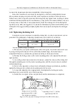
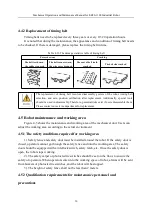
Because the J5 and J6 axes are both driven by timing belt, operation for a period of time
may cause loosening and decline of performance precision. The timing belt may also be worn
and cracked. If it is not replaced and maintained, transmission failure and economic loss may
occur. Therefore, it is recommended to check the running state of the timing belt regularly
(every half year). The loosening part should be tightened and the damaged should be replaced
Lubricant outlet of axis J3
Lubricant intake of axis J3
Lubricant outlet of axis J4
Lubricant intake
of axis J3


