background image

A419-00-880

Issue F Original

Instruction Manual

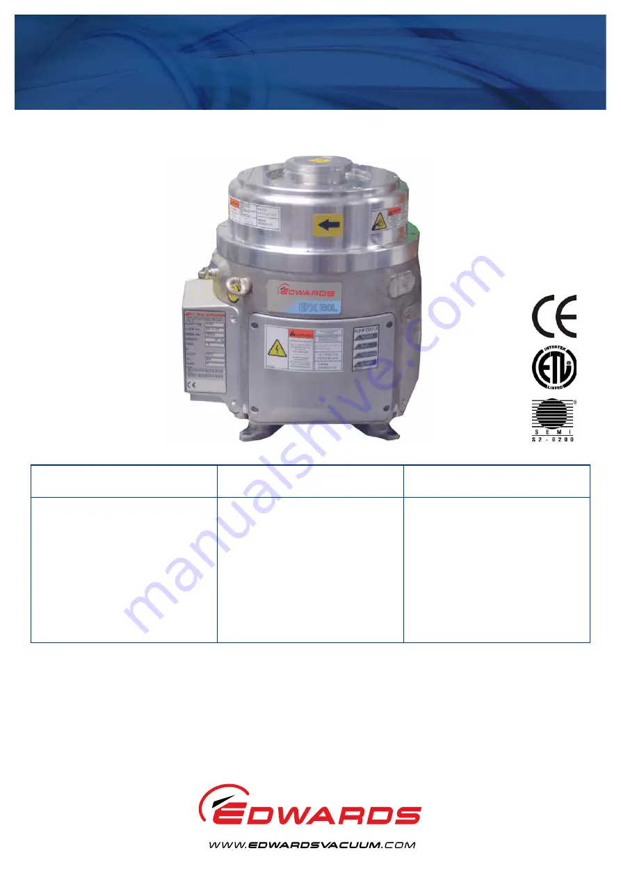
EPX HiVac Series Dry Vacuum Pumps

Description

EPX

EPX TWIN

Item Number

Item Number

EPX180L

A419-41-xxx

A419-61-xxx

EPX180N

A419-42-xxx

A419-62-xxx

EPX180LE

A419-43-xxx

A419-63-xxx

EPX180NE

A419-44-xxx

A419-64-xxx

EPX500L

A419-51-xxx

A419-71-xxx

EPX500N

A419-52-xxx

A419-72-xxx

EPX500LE

A419-53-xxx

A419-73-xxx

EPX500NE

A419-54-xxx

A419-74-xxx

Содержание EPX HiVac Series

Страница 1: ...EPX EPX TWIN Item Number Item Number EPX180L A419 41 xxx A419 61 xxx EPX180N A419 42 xxx A419 62 xxx EPX180LE A419 43 xxx A419 63 xxx EPX180NE A419 44 xxx A419 64 xxx EPX500L A419 51 xxx A419 71 xxx EPX500N A419 52 xxx A419 72 xxx EPX500LE A419 53 xxx A419 73 xxx EPX500NE A419 54 xxx A419 74 xxx ...

Страница 2: ...ve document s EN1012 2 1997 Safety Requirements Vacuum Pumps EN61010 1 2001 Safety Requirements for Electrical Equipment for Measurement Control and Laboratory Use EN61326 1998 Electrical Equipment for Measurement Control and Laboratory Industrial location Use EMC Requirements Class A Emissions UL61010A 1 Electrical Equipment for Laboratory Use Part 1 General First edition Requirements SEMI S2 030...

Страница 3: ...rocess gases 17 3 Installation 27 3 1 Safety 27 3 2 Unpack and inspect 27 3 3 Securing the EPX pump 28 3 4 Connect the inlet to your process system 28 3 5 Connect the outlet to your exhaust extraction system 29 3 6 Nitrogen purge EPX N series pumps 30 3 7 Leak test the system 31 3 8 Connect the cooling water supply 31 3 9 Connect to your emergency stop circuit 32 3 10 Connect the EPX pump to the e...

Страница 4: ...p 5 3 EPX twin 180L installation details position of additional exhaust port for EPX twin variants 6 4 EPX L labels refer to Table 3 8 5 EPX E dry pump 10 6 EPX N series dry pump 11 7 End User Controller EUC display 12 8 Speed curve mbar Pa 18 9 Speed curve Torr 18 10 Speed curve mbar Pa EPX and EPX Twin 19 11 Speed curve Torr EPX and EPX Twin 19 12 EPX L installation dimensions EPX500L shown 20 1...

Страница 5: ...e 4 9 4 EPX E Refer to Figure 5 10 5 EPX N Refer to Figure 6 11 6 General 15 7 Performance 15 8 Electrical data 16 9 Cooling water supply 17 10 Nitrogen supply 17 11 Materials in contact with process gas 17 12 Tool connectors and mating tool connector kits 34 13 Tool input signals to the pump system 34 14 Output signals from the pump system 35 15 EUC and PDT menu structure 39 16 Maintenance plan 5...

Страница 6: ...This page has been intentionally left blank A419 00 880 Issue F Page iv Edwards Limited 2007 All rights reserved Edwards and the Edwards logo are trademarks of Edwards Limited ...

Страница 7: ... EPX variant pump are equally applicable to the EPX Twin pump unless stated otherwise Differences between the two pump variants are restricted to power characteristics external connections to the exhaust extraction system and external dimensions appearance CAUTION Cautions are given where failure to observe the instruction could result in damage to the equipment associated equipment and process Th...

Страница 8: ...erial Warning toxic material Warning flammable material WARNING Edwards take no responsibility for damage or injury caused by improper use of the equipment WARNING The EPX Dry Vacuum Pump must only be used for the applications depicted in Figure 1 Incorrect use of the EPX system could invalidate your warranty Contact your local Edwards representative if you are unsure whether the EPX system is app...

Страница 9: ...mum speed If the pressure at the inlet increases the motor will slow down again The EPX pump is supported by four vibration isolators Figure 2 item 7 Pump protection sensors automatically shut down the pump if a fault condition arises refer to Section 1 3 The EPX pump is available in a number of different variants The nomenclature is arranged to help identify which variants are suitable for which ...

Страница 10: ...atically shut down by a pump protection sensor the Alarm LED is lit Figure 4 item 5 On the EPX N series of pumps a nitrogen purge flow switch is fitted to the Gas Module to monitor the total purge flow to the pump If the purge flow drops below 12 slm the warning LED on the front panel or EUC if fitted will light Figure 4 item 4 The pump will continue to run 1 4 LED status indicators Refer to Table...

Страница 11: ...ademarks of Edwards Limited Introduction A419 00 880 Issue F Figure 2 The EPX L dry vacuum pump 1 Pump inlet 2 Lifting eyebolt two positions 3 Protective earth stud M8 4 Cooling water inlet 5 TIM 6 Mains supply cable 7 Vibration isolator four positions 8 Exhaust 9 Cooling water outlet ...

Страница 12: ...ge 6 Edwards Limited 2007 All rights reserved Edwards and the Edwards logo are trademarks of Edwards Limited Introduction Figure 3 EPX twin 180L installation details position of additional exhaust port for EPX twin variants ...

Страница 13: ...re 4 item 5 This red LED is lit when the EPX pump has been automatically shut down because a pump protection sensor has operated Refer to Section 1 3 or because the inverter drive has failed Table 2 Connections Connection items Reference data Cooling water inlet and outlet Figure 2 items 4 and 9 Use these to connect your cooling water supply and return pipelines to the EPX pump refer to Section 3 ...

Страница 14: ...A419 00 880 Issue F Page 8 Edwards Limited 2007 All rights reserved Edwards and the Edwards logo are trademarks of Edwards Limited Introduction Figure 4 EPX L labels refer to Table 3 ...

Страница 15: ...e pump and suitable lifting equipment 11 Warning risk of high temperature Surface temperatures can exceed 65 o C during pump operation 12 Direction of rotation Arrow shows the correct direction of rotation of the rotor 13 Warning danger of injury from rotating parts Turn off and lock out all power prior to servicing 14 Water in The cooling water supply pipeline connects to the pump at this locatio...

Страница 16: ... be used to connect a fab wide network to allow remote monitoring and control of the EPX Dry Pump 3 Label Warning do not remove cover until 4 minutes after disconnecting power from the pump 4 RJ12 Connector This is used to connect the optional external PDT to the EPX Dry Pump 5 End User Controller accessory The End User Controller has an on board display and keypad that allows local control of the...

Страница 17: ...ter has failed connecting cooling water to a hot pump will cause severe damage to the pump Always allow the pump to cool for at least 20 minutes before connecting the cooling water 3 Label Warning do not remove cover until 4 minutes after disconnecting power from the pump 4 Gas supply fitting Connect the gas supply to this connection This compression fitting accepts 1 4 inch 6 35 mm diameter tube ...

Страница 18: ...5 The EPX E series of pumps can be manually operated using the EUC local display and keypad or remotely using a PDT if fitted it can also be controlled and monitored over the network which connects to the EPX pump through the Network connector Figure 5 item 2 When the EPX E series of pumps is controlled via the TIM the EUC simply monitors the status of the pump The EPX pump is compatible with Fabw...

Страница 19: ...CANCEL Figure 7 item 4 and ENTER Figure 7 item 6 buttons as described below Refer to Section 4 for a full definition of the menu structures and the display formats Status Press this button to select the Status menu This menu displays the current pump status Normal Press this button to select the Normal display Control Press this button to select the Control menu then take control or release contro...

Страница 20: ...A419 00 880 Issue F Page 14 Edwards Limited 2007 All rights reserved Edwards and the Edwards logo are trademarks of Edwards Limited This page has been intentionally left blank ...

Страница 21: ...g Maximum operating tilt angle 5o Handling The pump must not be laid on its side or inverted Topple angle 15 Maximum exhaust pressure 1200 mbar absolute Lubricating oil The EPX pump has a sealed lubricating oil system For health and safety information refer to the Material Safety Data Sheet for Fomblin 6 6 MSDS No P120 01 015 Ingress protection IP44 with inlet and exhaust connected E series pumps ...

Страница 22: ...r with a minimum contact gap of 3 mm The mains disconnect device AIC Amperes Interrupting Capacity must be rated to at least 10 000 A See clause 13 of SEMI S2 0200 and SEMI S8 for further details 200 V 17 5 A current limiting time delay Class CC fuse rated 600 V 400 V 10 A current limiting time delay Class CC fuse rated 600 V Installation overvoltage category Class II Pollution degree 2 Minimum pr...

Страница 23: ...ved from EPX pump 1 3 kW 5118 btu h 1 Minimum water flow rate 2 l min 1 31 7 US gallons h 1 Connectors Inlet Per customer specification Outlet Per customer specification Table 10 Nitrogen supply Gas Module Items Reference Data Nitrogen supply interface 1 4 inch 6 35 mm Tube Maximum supply pressure 7 barg 7 x 10⁵ Pa 100 psig Minimum supply pressure 3 0 barg 3 x 10⁵ Pa 45 psig Minimum purity 0 9995 ...

Страница 24: ...F Page 18 Edwards Limited 2007 All rights reserved Edwards and the Edwards logo are trademarks of Edwards Limited Technical data Figure 8 Speed curve mbar Pa Figure 9 Speed curve Torr 1 EPX500 2 EPX180 1 EPX500 2 EPX180 ...

Страница 25: ...wards Limited Technical data A419 00 880 Issue F Steady state speed curves showing the performance difference between the standard EPX L and EPX TWIN L variant Figure 10 Speed curve mbar Pa EPX and EPX Twin Figure 11 Speed curve Torr EPX and EPX Twin 1 EPX 180 2 EPX TWIN 180 1 EPX 180 2 EPX TWIN 180 ...

Страница 26: ...Issue F Page 20 Edwards Limited 2007 All rights reserved Edwards and the Edwards logo are trademarks of Edwards Limited Technical data Figure 12 EPX L installation dimensions EPX500L shown H 388 EPX180 H 397 EPX500 ...

Страница 27: ...Edwards Limited 2007 All rights reserved Page 21 Edwards and the Edwards logo are trademarks of Edwards Limited Technical data A419 00 880 Issue F Figure 13 EPX LE installation dimensions EPX500LE shown ...

Страница 28: ...A419 00 880 Issue F Page 22 Edwards Limited 2007 All rights reserved Edwards and the Edwards logo are trademarks of Edwards Limited Technical data Figure 14 EPX N installation dimensions EPX500N shown ...

Страница 29: ...Edwards Limited 2007 All rights reserved Page 23 Edwards and the Edwards logo are trademarks of Edwards Limited Technical data A419 00 880 Issue F Figure 15 EPX NE installation dimensions EPX500NE shown ...

Страница 30: ...hnical data Figure 16 Location of the pump centre of gravity from centre of the top of the inlet flange Pump X Axis Y Axis Z Axis EPX500L 2 23 3 08 202 69 EPX500LE 2 21 1 38 203 22 EPX500N 0 69 13 91 205 89 EPX500NE 0 69 12 24 206 36 EPX180L 2 50 3 15 196 39 EPX180LE 2 47 1 42 196 90 EPX180N 0 51 14 20 199 47 EPX180NE 0 51 12 49 199 93 ...

Страница 31: ...Limited Technical data A419 00 880 Issue F Figure 17 Gas module schematic 1 Supply port 2 Solenoid valve 3 Fixed pressure regulator 4 Check valve 5 Flow switch 6 Fixed flow restrictors 7 Gas ballast port 7a Alternative ballast port unused 8 Seal purge port 8a Alternative seal purge port unused 9 Connector ...

Страница 32: ...A419 00 880 Issue F Page 26 Edwards Limited 2007 All rights reserved Edwards and the Edwards logo are trademarks of Edwards Limited This page has been intentionally left blank ...

Страница 33: ...d under any circumstances z Vent and purge the process system before you start installation work z Disconnect the other components in the process system from the electrical supply so that they cannot be operated accidentally Further details are available from the Edwards publication Vacuum pump and Vacuum System Safety part no P300 20 200 3 2 Unpack and inspect 1 Use suitable lifting equipment att...

Страница 34: ...istributed across each of the vibration isolators The position of the centre of gravity is given in Figure 16 3 4 Connect the inlet to your process system WARNING Heavy objects can cause muscle strain or back injury Use suitable lifting equipment to move the pump Refer to Section 2 for the pump mass WARNING For safety reasons you must make sure that any frame you mount the pump on is securely fixe...

Страница 35: ...lied with a clear plastic protective cap on the inlet flange The cap prevents debris entering the pump during transit and protects the inlet flange from scratches The plastic cap must be removed prior to installation and operation of the pump Connect the inlet flange to a foreline or inlet reducing adapter using an Edwards centring O ring and claw clamps Refer to Section 2 1 for details of fitting...

Страница 36: ...t pressure that can be generated in your system and which can withstand the maximum temperatures that can be generated by your process conditions for example braided flexible bellows may be used for this purpose z The exhaust pipeline must be a minimum diameter of NW25 throughout 3 6 Nitrogen purge EPX N series pumps The following instructions apply to EPX N series pumps They are not applicable to...

Страница 37: ...ce with Table 9 CAUTION Cooling water must be provided commensurate with environmental conditions humidity and temperature such that the dew point is not reached CAUTION To prevent damage to the pump in the event of cooling water supply failure or a blockage in the pump we recommend that you incorporate a suitable flow switch in the cooling water return pipelines You can connect the outputs of the...

Страница 38: ...sible risk of trips z Wipe up any water spilt during installation to avoid possible risk of slips z Each EPX pump must be connected to an independent water circuit not in series with each other or other equipment z The cooling water supply should have a lock out tagout facility in accordance with SEMI S2 0200 clause 17 4 z We recommend that you incorporate a suitable ball type flow indicator in yo...

Страница 39: ...llowing statements z The mains disconnect device must be provided by the user and should be in a location satisfying the requirements of SEMI S8 where it is readily accessible z The mains disconnect device should not be located where there is any risk of personnel tripping on cables being obstructed or exposed to other hazards z The mains disconnect device should be marked as a disconnection devic...

Страница 40: ...ensed at 24 V 5 mA these inputs should not be linked together 2 Voltage inputs accept AC or DC voltage except SPI pins 15 and 16 between 15 V and 24 V selects the input as active below 5 V selects inactive 3 To ensure correct pump operation at least 10 seconds must be allowed between successive operations of the input signals WARNING Tool interface control signals are for control purposes only and...

Страница 41: ...9 HIT 19 and 37 HIT 12 and 30 Closed when pump running Warning SPI 7 and 8 MCM 7 and 8 TEL 9 and 21 E73 5 and 13 C3 4 and 8 HIT 14 and 32 Closed at all times no warnings are available on the EPX pump Alarm SPI 9 and 10 MCM 9 and 10 TEL 10 and 22 E73 6 and 14 LAM 1 and 14 C3 3 and 7 HIT 15 and 33 Closed when no alarm condition exists on the drive inverter See Section 4 3 and 4 4 for more informatio...

Страница 42: ...A419 00 880 Issue F Page 36 Edwards Limited 2007 All rights reserved Edwards and the Edwards logo are trademarks of Edwards Limited This page has been intentionally left blank ...

Страница 43: ...19 to 28 The following symbols and conventions are used in the menu diagrams These are flow lines Arrows on the lines show the direction of flow through a menu This symbol is used to connect different menus and shows the starting point or continuation point of a menu This symbol is used for the ENTER and CANCEL buttons and the four menu buttons Normal Status Control and Setup This symbol is used f...

Страница 44: ...ther specific uses of the CANCEL button are as follows z In the Switch On and Switch Off menus Figure 20 and 21 when you press CANCEL the menu is exited and the display reverts to that which was displayed before On or Off were pressed z In the Status menu Figure 23 when you press CANCEL the display shows the first two status parameters the defaults are EPX current consumption and power consumption...

Страница 45: ...five minutes the EUC or PDT will automatically exit the current menu and enter the Normal menu This facility known as timeout is available so that if the setup menu is entered and then EPX system is accidentally left unattended the menu is exited to prevent unauthorized use of the menu options 4 7 Menu structure The display and the control buttons are shown in Figure 7 The menu structure is shown ...

Страница 46: ...p and down buttons to change the third digit of the setup password to the correct value then press the ENTER button 5 If you have entered the correct password the display will then show SETUP MENU on the top line and the software version on the bottom line Figure 26 6 Press the down button or the up button twice the display will then show SETUP MENU on the top line and Normal display on the bottom...

Страница 47: ...ited 2007 All rights reserved Page 41 Edwards and the Edwards logo are trademarks of Edwards Limited End User Controller EUC and Pump Display Terminal PDT menus A419 00 880 Issue F Figure 19 EUC and PDT menu logic ...

Страница 48: ...Page 42 Edwards Limited 2007 All rights reserved Edwards and the Edwards logo are trademarks of Edwards Limited End User Controller EUC and Pump Display Terminal PDT menus Figure 20 Switch on menu Figure 21 Switch off menu ...

Страница 49: ...ds Limited 2007 All rights reserved Page 43 Edwards and the Edwards logo are trademarks of Edwards Limited End User Controller EUC and Pump Display Terminal PDT menus A419 00 880 Issue F Figure 22 Normal menu ...

Страница 50: ...0 880 Issue F Page 44 Edwards Limited 2007 All rights reserved Edwards and the Edwards logo are trademarks of Edwards Limited End User Controller EUC and Pump Display Terminal PDT menus Figure 23 Status menu ...

Страница 51: ...s Limited 2007 All rights reserved Page 45 Edwards and the Edwards logo are trademarks of Edwards Limited End User Controller EUC and Pump Display Terminal PDT menus A419 00 880 Issue F Figure 24 Control menu ...

Страница 52: ...Issue F Page 46 Edwards Limited 2007 All rights reserved Edwards and the Edwards logo are trademarks of Edwards Limited End User Controller EUC and Pump Display Terminal PDT menus Figure 25 Setup menu sheet 1 of 2 ...

Страница 53: ...ited 2007 All rights reserved Page 47 Edwards and the Edwards logo are trademarks of Edwards Limited End User Controller EUC and Pump Display Terminal PDT menus A419 00 880 Issue F Figure 25 Setup menu sheet 2 of 2 ...

Страница 54: ...880 Issue F Page 48 Edwards Limited 2007 All rights reserved Edwards and the Edwards logo are trademarks of Edwards Limited End User Controller EUC and Pump Display Terminal PDT menus Figure 26 Software version ...

Страница 55: ...Limited 2007 All rights reserved Page 49 Edwards and the Edwards logo are trademarks of Edwards Limited End User Controller EUC and Pump Display Terminal PDT menus A419 00 880 Issue F Figure 27 Select units menu ...

Страница 56: ...880 Issue F Page 50 Edwards Limited 2007 All rights reserved Edwards and the Edwards logo are trademarks of Edwards Limited End User Controller EUC and Pump Display Terminal PDT menus Figure 28 Select line menu ...

Страница 57: ... If the electrical supply to the EPX pump fails for only a few seconds the pump will continue to operate normally provided the run signal on the interface is maintained WARNING Do not operate the pump when the exhaust pipeline is restricted or blocked If you do the EPX pump can generate pressures up to 16 bar 1 6 x 10⁶ Pa and be damaged WARNING Inlet and exhaust temperatures can exceed 65 C in ext...

Страница 58: ...lectrical supply to the EPX pump and check that the Power LED Figure 4 item 2 goes on if the Power LED does not go on refer to Section 6 6 5 Check that the exhaust extraction system is not restricted and that any valves in the exhaust extraction system are open 6 Use your control equipment to set the pump run signal to the interface connector refer to Section 3 11 and check that the Run LED Figure...

Страница 59: ...nd the pump running pump warning and pump alarm status outputs should be closed If either or both of the other LEDs Figure 4 items 4 and 5 go on or if either or both of the pump warning and pump alarm status output signals are open refer to Section 6 6 5 6 Unplanned shutdown and alarms The EPX will automatically shutdown when a pump protection sensor operates refer to Section 1 3 or should the inv...

Страница 60: ...A419 00 880 Issue F Page 54 Edwards Limited 2007 All rights reserved Edwards and the Edwards logo are trademarks of Edwards Limited This page has been intentionally left blank ...

Страница 61: ...cal power Connection and disconnection of electrical signals WARNING There are no user serviceable parts within the EPX There is no requirement to remove the covers from the pump during normal operation Removing the covers could cause injury to people or damage to equipment WARNING Toxic flammable and corrosive chemicals may be present within the pump enclosure Ensure that the appropriate Personal...

Страница 62: ...f dangerous substances out of the system and leakage of air into the system refer to Section 3 7 z The inverter drive contains capacitors which store electrical energy after the pump has been shut down Wait at least four minutes after the pump has been shut down before you start any work on the electrical system of the EPX pump z The pump covers should not be removed as the pump contains sensitive...

Страница 63: ...e damaged or have overheated Check that all electrical connections are secure Tighten any connections that are loose 3 Inspect all process and exhaust pipelines check that they are not corroded or damaged Replace any pipelines that are corroded or damaged Check that all process and exhaust connections are secure Tighten any connections that are loose 6 4 Cleaning the pump CAUTION Do not use cleani...

Страница 64: ...ervice the EPX TWIN pump all variants Pump service requirements are largely determined by the pump s operating environment and application Service intervals range from 2 to 5 years Please contact your local Edwards service representative for further advice on a suitable maintenance schedule Main factors that will affect the service intervals of the EPX pump are z The ambient temperature in which t...

Страница 65: ...nt Ensure that the connections between your control equipment and the interface connector are correct to Section 3 11 The pump alarm status output signal is open and the Alarm LED is illuminated Has the cooling water supply failed Allow the EPX pump to cool down for at least 20 minutes Ensure that the cooling water supply is correctly connected to the EPX pump and is switched on and meets the flow...

Страница 66: ...RM 7001 INVERTER STOPPED Inverter running signal has not been received for more than 20 seconds whilst the pump should be running Usually caused by a dip in the 3 phase supply Remove power Check that the power supply is at full strength Apply power and restart the pump If the problem persists contact Edwards representative ALARM 17601 INVERTER FAULT Inverter has indicated a major fault trip condit...

Страница 67: ...pump to cool for approximately 30 minutes before disconnecting the water to the pump Drain the water from the cooling circuit Place a suitable container under the water outlet connector connection Figure 2 item 9 and connect a suitable connector along with a short length of hose for a drain Fit an airline maximum pressure 100 psi to a second spare connector and connect it to the pump water inlet c...

Страница 68: ... The majority of the EPX packaging is made from recycled and or recyclable materials Contact Edwards for further details Take particular care with the following z Fluoroelastomers which may have decomposed as the result of being subjected to high temperatures z Components which have been contaminated with dangerous process substances Contaminated components must be disposed of in accordance with l...

Страница 69: ... the part 8 2 Service Edwards products are supported by a worldwide network of Edwards Service Centres Each Service Centre offers a wide range of options including equipment decontamination service exchange repair rebuild and testing to factory specifications Equipment which has been serviced repaired or rebuilt is returned with a full warranty Your local Service Centre can also provide Edwards en...

Страница 70: ...A419 00 880 Issue F Page 64 Edwards Limited 2007 All rights reserved Edwards and the Edwards logo are trademarks of Edwards Limited This page has been intentionally left blank ...

Страница 71: ...ding 59 Flammable and toxic gases EPX N series pumps 52 G General operation 38 I Inputs 34 Inspect the pipelines and connections 57 Installation 27 L Leak test the system 31 LED status indicators 4 M Maintenance 55 Maintenance plan 56 Manual shut down 53 Materials in contact with process gases 17 Menu structure 39 N Nitrogen purge EPX N series pumps 30 Nitrogen purge system EPX N series pumps 17 O...

Страница 72: ...A419 00 880 Issue F Page 66 Edwards Limited 2007 All rights reserved Edwards and the Edwards logo are trademarks of Edwards Limited This page has been intentionally left blank ...

Отзывы: