A652–07–880 Issue D
Page 14
© Edwards Limited 2014. All rights reserved.
Edwards and the Edwards logo are trade marks of Edwards Limited.
Installation
3.8
Select the gas ballast flow rate (optional)
Note:
Use the procedure below to change the gas ballast flow rate after the E-LAB 2 has been used. The pump
must be switched off, allowed to cool and isolated from the electrical supply before doing the following
procedure.
The oil return assembly is supplied configured for high gas ballast flow rate. If required, adjust the gas ballast flow
rate using the following procedure.
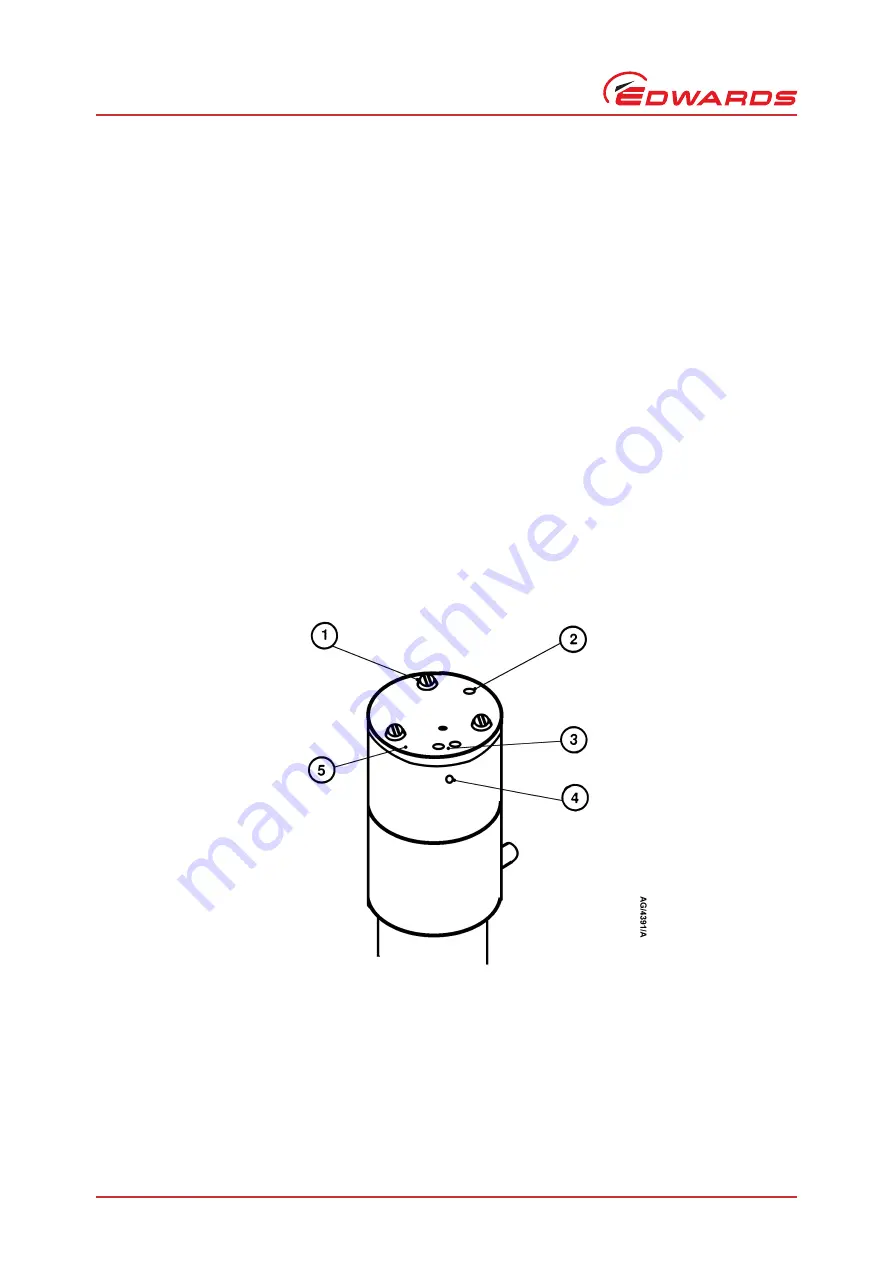
1. Undo and remove the three screws (
, item 1) which secure the restrictor plate (5); do
not
dismantle the
assembly.
2. The restrictor plate (5) has circular indentations (2 and 3); the position of these indentations with respect to the
indentation (4) on the oil return assembly identifies the gas ballast flow setting. Turn the restrictor plate to the
required position:
To select no gas ballast flow, turn the restrictor plate so that none of the indentations (2 and 3) are aligned
with the indentation (4) on the oil return assembly.
To select low gas ballast flow, turn the restrictor plate so that the single indentation (2) is aligned with the
indentation (4) on the oil return assembly.
To select high gas ballast flow, turn the restrictor plate so that the two indentations (3) are aligned with the
indentation (4) on the oil return assembly.
3. Refit and tighten the three screws (1).
Figure 6 - Select the gas ballast flow rate
1. Screws (3 off)
2. Indentation (low gas ballast flow position)
3. Indentations (high gas ballast flow position)
4. Indentation
5. Restrictor plate


