P/N 3101297-
EN • REV 04 • ISS 12NOV14
3 / 4
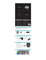
Figure 3: Wiring a single 5553 series speaker (non supervised)
Table 2: Power tap selector switch
Switch position
Impedance
25 V line SPL dB(A) at 10 ft.
70 V line SPL dB(A) at 10 ft.
1
5.0 K
-
-
0.9 W
93
2
2.5 K
-
-
1.8 W
96
3
1.3 K
0.48 W
91
3.8 W
98
4
666
0.94 W
93
7.5 W
101
5
333
1.8 W
96
15.0 W
103
6
89
7.5 W
101
Do not use on 70
V
7
45
15.0 W
103
Figure 4: Wiring multiple 5553 series speakers and/or supervised circuits
Caution:
To ensure proper supervision of connections, do not use
looped wires under the terminal screws. Break each wire run. Use both
sides of the terminal screws as shown.
Note:
To conform to UL requirements, wires must be connected as
shown in the wiring diagram. Wire size: 12 to 18 AWG (1.0 to
4.0 mm²
)
.
From amplifier
1/2 in. (12.7 mm) conduit entries
Power tap
selection switch
(see Table 2)
From supervised
or non supervised
amplifier
1/2 in. (12.7 mm) conduit entries
To next speaker
or end-of-line
resistor
Power tap
selection switch
(see Table 2)


