EDT VisionLink F Series Скачать руководство пользователя страница 10

EDT, Inc. 

2019 April 29 

10 

VisionLink F-series 

Image Capture and Display GUI 


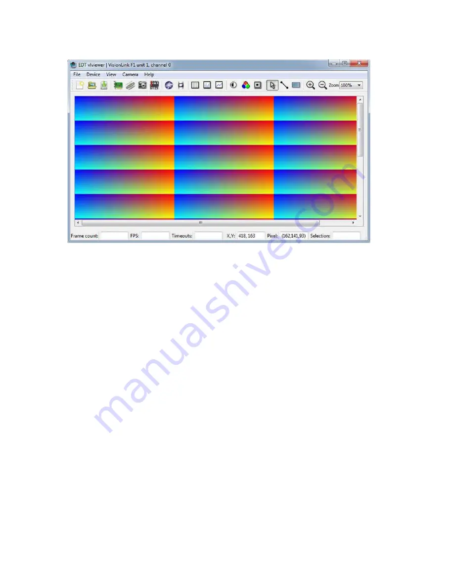
Figure 1.  Windows version 

 vlviewer 


To run the GUI... 


For Windows: Click the 

vlviewer 

desktop icon, or enter  

vlviewer 

at a command prompt. 


For Linux: Compile 

vlviewer 

(see 

Compiling vlviewer on page 22

); then, in the installation directory (see 

Instal- 

lation on page 8

), enter... 


vlviewer 

To invoke with other than the default (0,0) unit and channel, run... 


vlviewer -pdv

U_C 

...replacing 

with the unit number (useful if you have more than one VisionLink device) and 

with the channel 

number for multichannel devices (see 

Units, Connectors, and Channels on page 11

). 


For example, to run the GUI using board 0, channel 1, run... 


vlviewer -pdv0_1 

This example is useful if, for instance, you are using one board with two base-mode cameras and you want the GUI to 
access the camera on channel 1. 


NOTE 

In Windows, the command line is a property of the icon.To use an icon to access a unit or channel other than 0 (the 
default): copy and rename the 

vlviewer 

icon; then change its shortcut properties to use the command line with the 

option  

-pdv

U_C 

where  

is the unit and  

is the channel. 

If you have not yet configured the device for your camera, select your camera or simulator from the list and click 

OK


If the image window shows incorrect data (usually because the camera model has been changed since the last 
configuration), select 

Camera > Setup 

and choose the correct camera model. 


To access camera controls, use the GUI toolbar and menus. For details on available options, run... 


vlviewer --help 

...or bring up 

vlviewer 

and select the 

Help 

menu

Содержание VisionLink F Series

Страница 1: ...User s Guide VisionLink F Series Camera Link Frame Grabbers for PCI Express Date 2019 April 29 Rev 0012...

Страница 2: ...erence received including interference that may cause undesired operation This equipment has been tested and found to comply with the limits for a Class A digital device pursuant to part 15 of FCC Rul...

Страница 3: ...ors officers employees or agents be liable to Buyer for any consequential incidental or indirect damages including damages for business interruptions loss of business profits or information and the li...

Страница 4: ...ernal Triggering Pins 19 Simulation and Testing 20 Programming 21 Building or Rebuilding an Application 21 Compiling vlviewer 22 Firmware FPGA Configuration bit Files 22 Checking and Loading the Firmw...

Страница 5: ...EDT Inc 5 Footer Format 33 IRIG API 35 Revision Log 37...

Страница 6: ...IRIG B 019 14836 Full height backpanel 1 SDR 019 14852 Full height backpanel 2 SDRs 128 MB DDR3 IRIG B Lemo VisionLink F4 PCIe x4 Base TBD Half height backpanel full 019 14856 Full height backpanel 01...

Страница 7: ...ar EDT product go to edt com and open the relevant product page There you ll see links to that product s datasheet specifications user s guide and other resources In addition the resources below may b...

Страница 8: ...o save it elsewhere the package is saved in the default installation directory specified below The Windows default installation directory is C EDT pdv The Linux default installation directory is opt E...

Страница 9: ...ur camera model and operating mode For specifying a non default unit and channel and other options see initcam Example and Utility Applications on page 13 and the Camera Configuration Guide Related Re...

Страница 10: ...1 This example is useful if for instance you are using one board with two base mode cameras and you want the GUI to access the camera on channel 1 NOTE In Windows the command line is a property of the...

Страница 11: ...tion Units boards connectors and channels are always enumerated from 0 Figure 2 also shows the status indicator LEDs see LEDs on page 12 which are enumerated in the same way Figure 2 Illustration of e...

Страница 12: ...ly serial_baud serial_init serial_binit and other serial_ directives can be used to send serial commands when the system is initialized These are described in the EDT Camera Configuration Guide see Re...

Страница 13: ...tiondirectory Example and Utility Applications EDT provides a variety of example utility and diagnostic applications All can be run from the command line using Unix style options and arguments To help...

Страница 14: ...e camera settings such as integration time tune image acquisition in certain ways and detect errors Several of the most useful options are u unit The unit number if multiple boards are installed defau...

Страница 15: ...re03 bmp enter simple_take N 4 l 4 b picture simplest_take The simplest example application showing only how to open the device acquire an image check for timeouts and close the device For simplicity...

Страница 16: ...ewer pdvshow etc 4 Run dvinfo If multiple boards are installed you may find it helpful to add the optional flag u unit replacing unit with the unit number The default is 0 for the first board for deta...

Страница 17: ...the exposure time for example use set for the Dalsa 1M60 API subroutine pdv_set_exposure Camera specific range and units Triggered by EDT Board Fixed Period In this mode the board sends a fixed period...

Страница 18: ...C1 API subroutine pdv_set_exposure Microsecond units range 0 25500 External Trigger Direct to Camera In this mode a trigger is sent from an external source directly to the camera bypassing the board T...

Страница 19: ...0 and then is passed from the board to the camera via a camera control line typically CC1 to trigger line output Additionally a secondary TTL signal is sent from an external device to the board via tr...

Страница 20: ...ing In addition to the physical channels 0 and 1 each VisionLink frame grabber has a phantom channel 2 that reads self generated sample data useful for testing the board hardware and software with no...

Страница 21: ...n programming interface API for all supported operating systems so an application written for one EDT product is designed to work with other EDT products with minimal modification any exceptions such...

Страница 22: ...ur system and in your path at a minimum the Qt Core and Development libraries are required See http qt project org for Qt information and downloads The method for installing Qt4 varies depending on th...

Страница 23: ...the firmware on the board is the same as the firmware in the installation package If they differ you ll see an error message but this does not necessarily indicate problems if your application is wor...

Страница 24: ...or to the appropriate flash fpga subdirectory 2 Power off the host and board 3 To avoid later confusion remove any other EDT boards from the host 4 On the EDT board with the corrupted firmware move th...

Страница 25: ...ally a VisionLink board will not work in a slot dedicated to graphics display cards or a slot wired for fewer lanes than the number specified for instance a four lane board will not work properly in a...

Страница 26: ...dicate that the bus is too slow or the driver is misconfigured To correct this issue Verify that the camera configuration file is the correct one for your camera and operating mode see Setting the Cam...

Страница 27: ...irements Consider the number of cameras and the speed of the cameras you are using The bus bandwidth may be adequate for some configurations but inadequate for configurations with more or faster camer...

Страница 28: ...he underlying EDT DMA library The EDT message handler library provides generalized error and message handling for EDT software libraries and can be helpful in debugging your programs See the EDT messa...

Страница 29: ...inner shield ground inner shield ground 2 25 X0 Y0 Y0 15 12 X0 Y0 Y0 3 24 X1 Y1 Y1 16 11 X1 Y1 Y1 4 23 X2 Y2 Y2 17 10 X2 Y2 Y2 5 22 Xclk Yclk Yclk 18 9 Xclk Yclk Yclk 6 21 X3 Y3 Y3 19 8 X3 Y3 Y3 7 20...

Страница 30: ...k F1 FPGA boot select Normal Protected optional Lemo with adapter Quad LED 10 8 6 4 2 9 7 6 3 1 Test points optional secondary SDR26 1 Triggering pins DVAL LVAL FVAL PCLK primary SDR26 0 pin hole Not...

Страница 31: ...ed Reserved 10 Ground Ground LEMO CONNECTOR OPTIONAL Pin VisionLink F1 VisionLink F4 1 Trigger 1 Trigger 1 2 3 3V 3 3V 3 Trigger 0 Trigger 0 4 Trigger 0 Trigger 0 5 IRIG B IRIG B 6 Trigger 1 Trigger 1...

Страница 32: ...backpanel equipped with ribbon cabling and one or two 9 pin D connectors The diagram below illustrates the single D connector setup Connectors Transceivers Secondary Primary Any EDT framegrabber Trigg...

Страница 33: ...IRIG1 is now obsolete In addition to the IRIG time value the footer contains a frame counter as well as space for a 64 bit timestamp computed as Unix seconds and fractionalseconds For information on c...

Страница 34: ...For IRIG time the raw format is 6 bits seconds 6 bits minutes 5 bits hours 9 bits days 6 bits years Unix seconds seconds since 1 1 1970 without leap seconds 40 MHz count 12 4 u_int Counts using onboa...

Страница 35: ...ok 1 u_char pps_ok 1 u_char had_irig_error 1 u_char had_pps_error 1 status u_char reserved 3 double timestamp holds a 64 bit unix seconds time This must be filled in by software Irig2Record IRIG API I...

Страница 36: ...e DMA stream from the board this pointer will be overwritten when this buffer is used again enter irig2Record pdv_irig_get_footer PdvDev pdv_p u_char imagedata To compute the Unix time from the counts...

Страница 37: ...y A comprehensive user guide for vlviewer is available via the application s Help menu and replaced To specify options run with To invoke with other than the default 0 0 unit and channel run 20160129...

Страница 38: ...eries Frame Grabbers to F1 diagram added optional Lemo p 32 Additional External Inputs Via Berg or Optional Lemo updated pinouts 20140630 PH CH 0003 8 In Table 1 for VisionLink F4 Gen2 updated 850MB s...

Отзывы: