background image

SGC

3.2 COM2/3 PORT

COM2/COM3

 ports allow the connection to other telecontrol equipment with a PROCOME or MODBUS

protocol.

2.1 CONFIGURATION

The settings of this port are fully configurable as described in the “Communication Settings” section on
the “General configuration” chapter.

2.2 PROTOCOL AND CONNECTIONS

On 1TP and 2TP models, the connection with the other equipment is run over a serial RS485 link. An
RJ45 connector is used.

Connection   can   be   configured   either   half-duplex   or   full-duplex,   depending   on   the   setting   of   internal
jumpers. Default mode is half-duplex.

11

EDP


00110E4

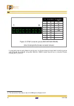
Illustration 5: COM2/3 (RS485) Pinout

(User looking to the female connector shown)

8

1

1 – RX +
2 – RX -
4 – TX -
5 – TX +
8 – GND

Содержание SGC Series

Страница 1: ...USER MANUAL SGC 00110E4 SGC SGC SWITCHGEAR CONTROL SYSTEM SWITCHGEAR CONTROL SYSTEM USER MANUAL ...

Страница 2: ...ote switch 7 1 5 Frontal and side microswitch 8 1 6 LCD display 8 2 2 Usage 9 2 1 Main screen 9 2 2 Navigation 9 2 3 Edition 9 3 SGC180 communications 10 3 1 COM1 Port 10 1 1 Configurations 10 1 2 Protocol and connection 10 3 2 COM2 3 Port 11 2 1 Configuration 11 2 2 Protocol and connections 11 4 Communications for SGC195 devices 12 4 1 COM1 port 12 1 1 Protocol and Connections 12 4 2 COM4 Port 14...

Страница 3: ... 3 2 Signals 27 3 3 Settings 28 3 4 Operation 29 6 4 Circuit breaker failure monitoring 31 4 1 Description 31 4 2 Signals 31 4 3 Settings 31 4 4 Operation 32 6 5 Circuit Breaker Supervisor 33 5 1 Description 33 5 2 Signals 33 5 3 Settings 33 5 4 Operation 33 5 4 1 KA2 Counter 33 5 4 2 Max breaking count 33 5 4 3 Trip operations 33 6 6 Protection functions 34 6 1 Overcurrent 50 51 50N 51N 34 6 1 1 ...

Страница 4: ...able 15 Sensitive neutral FPD settings 21 Table 16 VPD signals 24 Table 17 VPD Settings 25 Table 18 Sectionaliser signals 28 Table 19 Sectionaliser settings 28 Table 20 CB Monitoring signals 31 Table 21 CB failure settings 31 Table 22 Circuit breaker supervisor signals 33 Table 23 Circuit breaker supervisor signals 33 Table 24 Protection function signals 50 51 50N 51N 35 Table 25 Protection functi...

Страница 5: ...on 9 Example of sectionalizer automatism working 30 Illustration 10 Operation and state diagram of sectionaliser algorithm 30 Illustration 11 Command execution order 32 Illustration 12 Operation zones diagram 39 Illustration 13 Connection diagram 48 Illustration 14 SGC195 Connection diagram 49 Illustration 15 Connection example 1 Line Circuit Breaker 2 Protection Transformer Circuit Breakers 50 IV...

Страница 6: ...tage current and power SGC195 SGC180 with an integrated multiprotocol RTU in small form factor It s an ideal solution for space constrained remote control applications such as overhead line circuit breakers For switchgear manufacturers the SGC is ready to be integrated with in switchgear itself given its small size and short depth This kind of installation is usually the most economical as the fie...

Страница 7: ...ts Power supply Processing module Analog measurement module Digital I O module Communications module 00110E4 EDP 2 Illustration 2 Block diagram ADC ADC COM PORTS CPU RAM ROM RTC LOCAL BUS DSP SAMPLE BUFFER POWER SUPPLY Current Voltage Analog inputs ED DO DI RELAYS OPTOS ...

Страница 8: ... is guaranteed by these functions Open close operation monitoring Maneuver counter kA2 counter 1 2 1 3 TIME SYNCHRONIZATION Time is synchronized via the communication protocol ensuring time stamps coherence between primary and secondary stations The SGC also provides an internal real time clock so timekeeping is accurate even when the power or communication link is down 1 2 1 4 SWITCHGEAR CONTROL ...

Страница 9: ...t impedance of the voltage inputs Indirect mode substituting the preinstalled voltage indicator on the switchgear with an EDP HVR3A voltage meter The HVR3A doubles its function as a voltage indicator so it can be installed in place of the current voltage indicator and as a voltage amplifier with an analog output ready to be connected to the SGC with no loss of phase or magnitude information More o...

Страница 10: ... It is always possible to monitor and configure the unit locally with a computer connected to the frontal communications port with our software qtAjustes2 The software functions are Monitor and download of settings files Direct reading of digital inputs outputs and analog measurements Capacitive transducer field calibration for its use with a HVR3A meter Simulation of events in order to check the ...

Страница 11: ...Ds in the communication device see iGrid iRTU communications device manual 1 2 INDICATOR LEDS FOR SGC195 DEVICES The SGC195 device has 13 state LEDs in the front panel VSGC Shows supply voltage presence on the switchgear control unit SCU VRTU Shows there are supply voltage presence on the remote terminal unit RTU COM 4 Shows receiving data Rx and transmitting data Tx through the COM4 port COM 1 Sh...

Страница 12: ...enu together with the desired key I to close O to open A confirmation screen will appear where the key B will be pushed to accept it or the key C will be pushed to cancel it 1 4 LOCAL REMOTE SWITCH There is a two position switch in the frontal panel to choose the device operating mode between local and remote The operating mode of the device can be known because is shown by 2 LEDs placed in both s...

Страница 13: ...tenance start Remaining side microswitchs 1st 3rd doesn t have a specific use but they will be implemented in next releases 1 6 LCD DISPLAY The LCD Display shows the most part of the data The main screen are composed by these elements LED labels name of the associated states to the LEDs Line name Identifier to the Switchgear control module Voltage presence the voltage presence of each phase is sho...

Страница 14: ...inputs submenus with its corresponding contextual navigation menu that will have the next options Back A Goes back to the previous menu Edit B If the selected value is editable this push button will start the edition mode Previous C Moves the cursor towards the previous element in the screen Next D Moves the cursor towards the next element in the screen 2 3 EDITION To edit any value we push the ed...

Страница 15: ...1 CONFIGURATIONS COM1 has always the same configuration parameters Bit rate 19200bps Data bits 8bit Parity None Stop bits 1 Flow control None 1 2 PROTOCOL AND CONNECTION This port can be connected to any RS232 serial port with a standard DB9 connector cable Communication can be established with any terminal software4 but the use of the provided software is preferred for user convenience 4 Device i...

Страница 16: ...n the General configuration chapter 2 2 PROTOCOL AND CONNECTIONS On 1TP and 2TP models the connection with the other equipment is run over a serial RS485 link An RJ45 connector is used Connection can be configured either half duplex or full duplex depending on the setting of internal jumpers Default mode is half duplex 11 EDP 00110E4 Illustration 5 COM2 3 RS485 Pinout User looking to the female co...

Страница 17: ...ble ports in the SGC195 devices 4 1 COM1 PORT COM1 is a RS232 modem RS232 RS422 RS484 software configurable port with 3kV isolated that connects the SGC195 device with the either control center or other communication devices 1 1 PROTOCOL AND CONNECTIONS Data transmission to the control center can be configured by using any of the following protocols IEC60870 5 101 DNP3 0 Modbus RTU In addition it ...

Страница 18: ...85 User looking to the female connector shown To work with protocols using RS232 modem mode a connector Phoenix Contact MC 1 5 9 ST 3 5 will be used Whereas the protocols using either RS422 or RS485 modes they will use a connector Phoenix Contact MC 1 5 5 ST 3 55 5 This connector is the same as used in COM4 port at chapter 4 2 2 1 13 EDP 00110E4 1 9 ...

Страница 19: ... by means of the next protocols PROCOME MODBUS To connect with the communication COM4 unit a connector Phoenix Contact model MC1 5 5 G 3 5 of 5 contacts is used with the next configuration Pin Mode RS422 RS485 1 Rx 2 Rx 3 Tx 4 Tx 5 GND Figure 7 COM4 connector pinout RS232 RS422 RS485 User looking to the female connector shown To work with protocols using either RS422 or RS485 mode a connector Phoe...

Страница 20: ...ice connecting a computer to the USB_OTG MGMT port computer Windows 9 installed driver will be used When Windows doesn t installs correctly the driver iGrid_iRTU_driver inf will need to be installed to the computer To gain access through FTP to the RTU we will use the current SGC195 device IP address indicating user isupport and password irtusupport in your FTP manager10 With the computer connecte...

Страница 21: ...B pendrive with the folders shown previously to the USB type A port 3 Plug the voltage supply and starts SGC195 device 4 When the USB pendrive is connected usually a LED from pendrive is on the upgrading process will start During the upgrading process A and B LEDs will start to blinking every 500ms See table 2 5 The upgrading process will take around 40 seconds Once this process is done A and B LE...

Страница 22: ...GS The physical inputs and outputs are assignable to any equipment internal signal with the settings shown in this section It is possible to logically negate the signals whether the inputs as the outputs The digital inputs can also be disabled in order to avoid either to log or to send unintended events or due to malfunction of the connected equipment The assignment of signals can be done through ...

Страница 23: ...SGC To Local When logic high the SGC is in local mode any remote operation is disabled Manually close When logic high the SGC sends a close command to the switchgear Manually open When logic high the SGC sends an open command to the switchgear For each line LCB Closed Line circuit breaker is closed LCB Open Line circuit breaker is open ECB Closed Earthing circuit breaker is closed ECB Open Earthin...

Страница 24: ...e leds any command signal can be assigned to them with these settings SETTING DESCRIPTION VALUE LEDs List of assigned signals to LEDs Module unit and signal Table 10 LED settings 3 2 ID INFORMATION A brief string describing the controlled equipment For reference only 19 EDP 00110E4 ...

Страница 25: ... an impulsive signal only activations can be read 2 Fault detection signaling it becomes logical 1 when a fault is detected and it is reset to 0 according to the reset settings 3 Directional detection indicators signal the fault direction OUTPUTS Fault pass detection Fault pass detected either phase or neutral Phase Fault pass detection Phase Fault pass detected Neutral Fault pass detection Neutra...

Страница 26: ...isables function Timed Reset Tri 1 250 m 1 m Directional ES FS Table 12 General FPD settings 1 3 2 PHASE DETECTOR NAME RANGE STEP OTHER Enable ON OFF Current threshold 100 1000 A 1 A Primary setting Table 13 Phase FPD settings 1 3 3 NEUTRAL DETECTOR NAME RANGE STEP OTHER Enable ON OFF Current threshold 5 100 A 1 A Primary setting Table 14 Neutral FPD settings 1 3 4 SENSITIVE NEUTRAL DETECTOR OPTIO...

Страница 27: ... fault is cleared and no signaling is done If there is no voltage then the fault is deemed permanent and thus signaled For the correct operation of the module the detection time settings must be coherent with voltage detector time settings and recloser configuration Fault pass signaling is reset by one of these procedures 1 Service restored when voltage presence is detected during Tri seconds the ...

Страница 28: ... DETECTION CURRENT PHASE HOMOPOLAR I Ip Tv CLEAR FAULT Ts I Fault threshold current Ip Line current To Fault detection time Tv Fault verification time Tri Service restore reset time Ts Timed reset time Service restored a Service restored afeter Tri b Timed reset To OPEN CLOSE CIRCUIT BREAKER SIGNALLING DETECTION CURRENT PHASE HOMOPOLAR I Ip Tv CLEAR FAULT Tri To Tri VOLTAGE PRESENCE VOLTAGE PRESEN...

Страница 29: ...ioned algorithms 2 2 SIGNALS OUTPUTS Voltage Presence A Voltage on line A is above threshold Voltage Presence B Voltage on line B is above threshold Voltage Presence C Voltage on line C is above threshold Voltage Presence Voltage on line A B C is above threshold Phase Open Fail There is no voltage presence on one or two phases Voltage Presence Signal Timed version of Voltage Presence signal Phase ...

Страница 30: ...side the presence overvoltage threshold This alarm is disabled in a three phase undervoltage situation The signal outputs are timed versions of the logical signals for filtering out line transients and avoid false event logging The swell sag voltage detection unit is monitoring the voltage rate within phases When this go out of its nominal range after passed a minimum time the monitoring of the sa...

Страница 31: ...6 FUNCTIONS 00110E4 EDP 26 Illustration 8 VPD unit logic diagram ...

Страница 32: ...utomatism will not be active in case that the device is working in local mode Two different operating modes are possible In local out of service The automatism will be out of service when the device change to local mode and will need a command to enable the automatism when the device goes back to the remote mode In local blocked The automatism will be blocked when the device change to local mode a...

Страница 33: ...CB close command Remotely command the unit to issue the CB closing Enable automatism Automatism enable Disable automatism Automatism disable Table 18 Sectionaliser signals 3 3 SETTINGS The sectionaliser algorithm can be configured to work with up to 100 reclosing of fixed time NAME RANGE STEP OTHER Enabled ON OFF Recloser count 1 100 1 Reclosing time 1 500 s 0 5 s Command time 0 1 15 s 0 1 s Switc...

Страница 34: ... reclosing cycle is assumed Then the T timer is restarted If there is not a fault pass detection during the T time or a fault is detected but with voltage presence on the line it is assumed the fault has been cleared so the automatism returns to the initial state If the current reclosing cycle is the last one programmed the voltage presence is checked once the timer is expired If the fault has bee...

Страница 35: ... BREAKER FAULT PASS VOLTAGE PRESENCE OPEN COMMAND YES NO YES NO CLOSED OPEN YES NO a Reclosing count 2 Failed reclosings 1 N 0 N 1 N 2 T T STATE WATCH RUNNING CYCLE LAST RECLOSING WATCH CIRCUIT BREAKER FAULT PASS VOLTAGE PRESENCE OPEN COMMAND YES NO YES NO YES NO b Reclosing count 2 Failed reclosings 2 N 0 N 1 N 2 T T STATE WATCH RUNNING CYCLE LAST RECLOSING WATCH ...

Страница 36: ...g CB opening CB Failure I Failure detected during CB closing Motor Failure Failure detected on motor operation INPUTS LCB Open Open signaling from the CB LCB Closed Closed signaling from the CB Motor Motor operating signaling from the CB Table 20 CB Monitoring signals 4 3 SETTINGS NAME RANGE STEP OTHER Open failure threshold current phases 0 100 A 5 A 0 disables checking Open failure threshold cur...

Страница 37: ... but there is no current checking and the failure signal is CB Failure I There is also an optional motor failure checking to prevent it from running continuously when there is a problem in its control circuit This is done by triggering the Motor Failure Signal when the motor is on more than the Maximum motor time setting This signal can be assigned to a digital output to open the motor circuit The...

Страница 38: ...mum number breaking operations 0 248 1 0 disables the alarm Breaking counter time window 60 43200 s 1s Table 23 Circuit breaker supervisor signals 5 4 OPERATION 5 4 1 KA2 COUNTER This function keeps the sum of kA2 from breaking operations of the circuit breaker on a non volatile memory When this number exceeds a preprogrammed threshold a signal is activated as an alarm The initial value is defined...

Страница 39: ...are protections against shortcircuits between phases 50 or phases and neutral 50N This is done by an instantaneous breaking command when the current is above a configurable threshold The 51 51N functions are protections against overloads between phases 51 or phase neutral overcurrents 51N This is done by a timed breaking command configurable as a timer or a current dependent timer 00110E4 EDP 34 ...

Страница 40: ... 51N Trip 50 Tripping order from function 50 Trip 50N Tripping order from function 50N Blocked The unit is in blocked state MEASUREMENTS Value peak pickup phases Gives the maximum value of a phase pickup process Value peak pickup neutral Gives the maximum value of a neutral pickup process COMMANDS Pickup Signal Reset Resets the pickup signalization INPUTS Block The unit is disabled Direction The u...

Страница 41: ... times 0 1 t Neutral additional instantaneous time 0 1 10 s 0 1 s Table 26 Protection function 50N 51N settings 6 1 4 OPERATION PICKUP When the line current reaches the pickup level the protection function starts the timing The return from pickup threshold is 95 of the nominal pickup threshold OVERCURRENT BLOCKING To ease the protection coordination with other elements i e fuses a programmable blo...

Страница 42: ...nverse time The inverse time characteristic is determined by the following equation The K and n values for each curve family are N I Normal Inverse K 0 14 y n 0 02 V I Very Inverse K 13 5 y n 1 E I Extremely Inverse K 80 y n 2 D T Definite time DI Disabled 37 EDP 00110E4 t K I Ia n 1 Where I Line current A Ia Pickup current A t Time s ...

Страница 43: ...al unit is functioning Direction Sets the direction of the allowing zone 0 Output 1 Input COMMANDS Enable directional Enables the directional functionality Switch direction Switches the current direction of the allowing zone Table 27 50 51 50N 51N Protection function signals 6 2 3 SETTINGS NAME RANGE STEP OTHER Enable ON OFF Maximum torque angle 0 359º 1º Direction In Out Polarizing voltage 0 5 60...

Страница 44: ...ine voltage is too low The allowing blocking signal is routed to other protection units overcurrent protection FPD When they have the directional flag enabled they can be blocked by this unit The following Illustration shows a phasor diagram of the operation zones 39 EDP 00110E4 Illustration 12 Operation zones diagram 0º 90º 270º MTA Input Output ɸi ɸv Allowing zone Blocking zone Transition zone 5...

Страница 45: ...ive readings Neutral Nominal Current 1 5000 A 1 A For relative readings Neutral Nominal Voltage 1 100 kV 1 kV For relative readings Calculate neutral current On Off Calculate neutral voltage On Off Table 30 Measurement function settings The voltage transformer connection establish if the input voltage are line ground or line line voltage In each case the other value is internally calculated by the...

Страница 46: ...rent IN Angle Value Angle relative to IA Voltage UB Angle Value Angle relative to UA Voltage UC Angle Value Angle relative to UA Voltage UN Angle Value Angle relative to UA Active Power Active power computed from voltage current kW Reactive Power Reactive power computed from voltage current kVAr Power Factor Power factor 1 PF 1 THD Total harmonic distortion Average Phase to Phase Voltage Average o...

Страница 47: ...veform before the trigger occurs allowing the context of the capture to be analyzed with more ease Up to 8 captures can be stored on the SGC when this number is reach the module is disabled If Overwrite Oldest setting is enabled the oldest capture data is erased from memory to free space for a new one In this mode the module is always ready for a new capture 6 4 2 SIGNALS COMMANDS Manual trigger M...

Страница 48: ...e the lighting voltage presence indicators found in MV switchgear being small enough to fit in space constrained applications It can be also used with any meter with a low voltage AC inputs MULTIFUNCTION PROTECTIVE RELAY RS9 The RS9 is a multifunction protective relay with a rich graphical user interface covering most applications needing a protective relay Directional overcurrent 50 51 50N 51N 67...

Страница 49: ...ection 2 5 mm2 Option 1 3 isolated inputs and 5 inputs with 1 common Option 2 6 isolated inputs and 2 groups of 5 inputs with 1 common Digital Outputs Nominal Voltage 250 V Max Load Current 8 A Cabling section 2 5 mm2 Configuration DPDT Relay Output Analog Inputs Current Nominal current 1 or 5 A Nominal Consumption 0 05 VA Thermal Current Ith 5 In permanent 100 In 1s Accuracy AI model In I 1 2 In ...

Страница 50: ...ltage Option 12 220 350 Vac Option 24 48 110 150 Vac Option 110 275 Vac Accuracy AI model 0 8 Un U Un 0 2 Other Models 0 8 Un U 1 2 Un 1 Sampling Analog Bandwidth 64 samples cycle Analog Bandwidth 1 kHz Other Temperature range 10 ºC 55 ºC Body Dimensions W x H x L 83 x 177 x 116 mm Weight 1 5 kg 45 EDP 00110E4 ...

Страница 51: ... Communications Digital IO Options 1A In 1A 12 9 18 Vdc M Rear Non communicable 1 8 DI 4 DO Non UI 5A In 5A 24 18 36 Vdc D DIN rail 1TP 1x RS485 RJ45 2 16 DI 8 DO U With UI19 48 36 72 Vdc 2TP 2x RS485 RJ45 No IO 110 36 150 Vdc ETH Ethernet 220 85 264 Vac 19 User Interface With this option the device adds LCD display keyboard and Remote Local switch to allow do local maintenance manoeuvres 00110E4 ...

Страница 52: ...loser Oscillography Configurable inputs Configurable outputs Inverse logic signals Event log Shell Real time clock Current inputs 3F N 3F N 3F N Voltage inputs 3F 3F 3F Digital I O Options 1 2 1 2 1 2 Configurable LEDs 0 0 6 Display and keyboard PROCOME 101 104 DNP3 Modbus 20 This indicates that for this option contact to Electrónica Digital de Protección S A to activate it in the model asked for ...

Страница 53: ...10 SCHEMATICS 10 SCHEMATICS 00110E4 EDP 48 ...

Страница 54: ...SGC 49 EDP 00110E4 ...

Страница 55: ...10 SCHEMATICS 00110E4 EDP 50 Illustration 13 Connection diagram ...

Страница 56: ...SGC Illustration 14 SGC195 Connection diagram 51 EDP 00110E4 ...

Страница 57: ...11 SIZE 00110E4 EDP 52 Illustration 15 Connection example 1 Line Circuit Breaker 2 Protection Transformer Circuit Breakers ...

Страница 58: ...SGC 11 SIZE 53 EDP 00110E4 Drawing 1 Front and side views of SGC180 and SGC195 devices ...

Страница 59: ...11 SIZE Drawing 2 Top and bottom view of SGC180 device 00110E4 EDP 54 ...

Страница 60: ...SGC Drawing 3 Top and bottom view of SGC195 device 55 EDP 00110E4 ...

Страница 61: ... EN 60255 5 Electrical disturbance testing 2 5kV longitudinal 1kV cross class III according UNE 21136 22 1 Fast transient 2kV according UNE EN 61000 4 4 class III UNIPEDE ref NORM SPEC 13 Automation and Control Apparatus for Generating Stations and Substations Electromagnetic Compatibility Requirements 00110E4 EDP 56 ...

Страница 62: ...r relays Synchronous checkers Communication equipment Converters Timers Flow Current checker Circuit breaker panels If you require any further information do not hesitate to contact us MANUFACTURER NOTE This device can be modified in order to introduce improvements and might not match up with this handbook Cl Anselmo Clave 80 bajos 08100 Mollet del Valles Barcelona CIF A64139686 Distribuidor 57 ED...

Отзывы: